

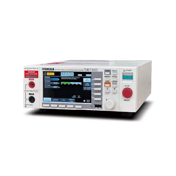
Insulation Resistance Tester
TOS7300
Price range: 150,000円 through 165,000円
- Output voltage range: 25 Vdc to 1000 Vdc
- Resistance measurement range: 0.001 MΩ to 10.00 GΩ
- Upper/lower limit judgement, short-circuit detection, and contact check function
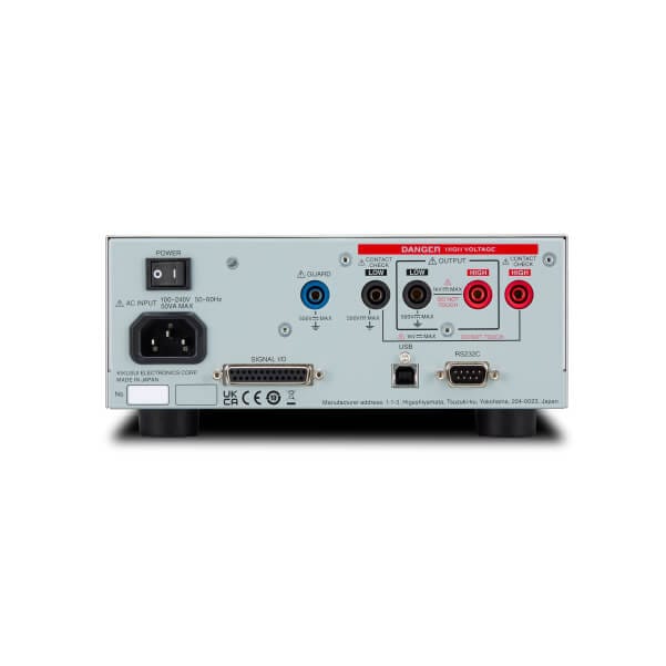
- RS-232C / USB interface standard
- WITH LAN models come standard with a LAN interface
- Equipped with a color LCD
| Image | SKU | Interface | 標準価格 | WEBかんたんお見積り |
|---|---|---|---|---|
 | TOS7300 | RS232C, USB | 150,000円 (税込:165,000円) | |
 | TOS7300 with LAN | RS232C, USB, LAN | 165,000円 (税込:181,500円) |

Line-up
| Image | SKU | Interface | 標準価格 | WEBかんたんお見積り |
|---|---|---|---|---|
| TOS7300 | RS232C, USB | 150,000円 (税込:165,000円) | |
| TOS7300 with LAN | RS232C, USB, LAN | 165,000円 (税込:181,500円) |
Product Overview
It is suitable for research and development facilities, quality assurance testing and standard certification agency testing facilities, production lines, and more.
In the TOS7300 series, the output voltage can be freely set from 25 V to 1000 Vdc in 1 V steps (compliant with the output characteristics of JIS C 1302), making it an insulation resistance tester suitable for a wide range of applications—from electrical/electronic components to complete electrical and electronic equipment. Test settings, summaries, and diagrams are clearly visible on 4.3-inch color display. This series also comes standard with USB 2.0, USB compliant with USB-TMC, and RS232C. WITH LAN models come with a LAN interface. When used together with external control via Signal I/O, you can build highly flexible automated test setups. In addition, TOS7301 and TOS7301 WITH LAN models support dV judgment, which helps protect the EUT from damage during testing. They also have faster selectable measurement times (Aperture Time) and provide a graphical display of measurement data during testing. These models are ideal not only as insulation resistance testers for secondary batteries where tight takt times are required, but also for R&D applications across a wide variety of materials.
| Supported Features / Models | TOS7300 | TOS7300 WITH LAN | TOS7301 | TOS7301 WITH LAN |
|---|---|---|---|---|
| Insulation resistance test (IR) DC 25 V to 1000 V | ✓ | ✓ | ✓ | ✓ |
| Communication interface USB2.0, RS232C | ✓ | ✓ | ✓ | ✓ |
| Communication interface LAN | n/a | ✓ | n/a | ✓ |
| Data storage / CSV export | ✓ | ✓ | ✓ | ✓ |
| Graphing of Test Result Data | n/a | n/a | ✓ | ✓ |
| dV pass/fail function to help protect the EUT from damage | n/a | n/a | ✓ | ✓ |
| Measurement time: set as fast as 10 ms | n/a | n/a | ✓ | ✓ |
| Contact check function | ✓ | ✓ | ✓ | ✓ |
Easy operation for fast, safe, reliable testing!!
High-Speed Measurement Times
Boost productivity with speeds down to 10 ms!
Select a measurement time from 10 ms*/ 16.66 ms/ 20 ms/ 100 ms. Shorter measurement times help reduce takt time.
*TOS7301 and TOS7301 WITH LAN only
Safe and Reliable
Includes contact check and short-circuit detection!
Features a contact check function that detects poor connections to the EUT or broken test leads, plus a short-circuit detection function that identifies a shorted EUT before high voltage is applied to help prevent EUT damage.
Color LCD Screen for Improved Visibility!
Equipped with a 4.3-inch color display!
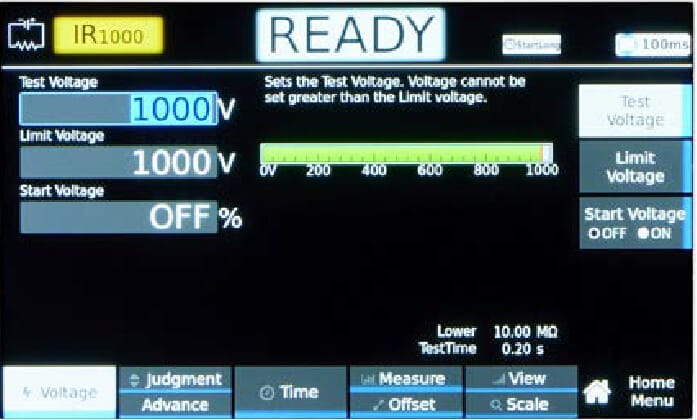
Test settings, overviews, and diagrams are clearly visible on the 4.3-inch display, making operation more intuitive.
Versatile Interfaces
Flexible automated testing made easy!
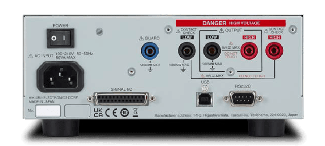
All models come standard with USB 2.0, USB-TMC compliant USB, and RS232C interfaces. In addition, WITH LAN models allow the use of a LAN interface.
Specifications
Insulation Resistance Test
Output
| Item | Specifications | |
|---|---|---|
| Output voltage | 25 Vdc to 1000 Vdc | |
| Output setting accuracy | ±(1.0% of setting + 2V) | |
| Output setting range | 0 V to 1025 V | |
| Output setting regulation | 1 V | |
| Max. rated load | 1 W (1000 V/1 mA) | |
| Max. rated current | 1 mA | |
| OUTPUT terminal | Output form | Floating |
| Isolation voltage | ±500 Vdc (including the output of the TOS73 series) | |
| Ripple | 1 kV no load | 5 Vp-p or less |
| Max. rated load | 10 Vp-p or less | |
| Voltage regulation | 1 % or less (when changing from maximum rated load to no load) | |
| Constant current charge function | Charge current 2 mA | |
| Short-circuit current | 10 mA or less | |
| Discharge function | At the end of the test, constant current discharge, discharge current 10 mA (TYP), Maximum capacitance: 2 μF *1 | |
| Output voltage rise time | 1 ms or less (when Voltage rise time (Rise Time) is OFF) | |
| Output voltage monitor function | If the output voltage exceeds ±(10 % of setting + 5 V), the output is turned off, and the protection function is activated | |
*1. Maximum capacitance that can be discharged within 0.2 seconds in a insulation resistance test. Tests can still be conducted beyond the maximum capacitance, but the discharge time will increase.
Voltmeter
| Item | Specifications |
|---|---|
| Measurement range | 0 Vdc to 1200 Vdc |
| Resolution | 0.1 V |
| Accuracy | ±(1 % of reading + 1 V) |
Resistance meter
| Item | Specifications | |
|---|---|---|
| Measurement range | 0.001 MΩ to 10.00 GΩ (in the range of maximum rated current of 1 mA to 40 nA) | |
| Accuracy *1 (i: measured current) (R: measurement resistance) | 40 nA ≤ i ≤ 100 nA | 200.00 MΩ ≤ R < 10.000 GΩ: ±(20 % of reading) |
| 100 nA < i ≤ 200 nA | 100.00 MΩ ≤ R < 5.000 GΩ: ±(10 % of reading) | |
| 5.000 GΩ ≤ R < 10.000 GΩ: ±(20 % of reading) | ||
| 200 nA < i ≤ 1000 nA | 10.000 MΩ ≤ R < 5.000 GΩ: ±(5 % of reading) | |
| 1 μA < i ≤ 2 mA | 0.001 MΩ ≤ R < 10.000 MΩ: ±(2 % of reading + 5 digit) | |
| 10.000 MΩ ≤ R < 1.000 GΩ: ±(2 % of reading) | ||
| Display (R: measurement resistance) | 10.000 GΩ < R | Over |
| Hold feature | The resistance measurement after a test is finished is held while the pass judgment is displayed. | |
| Offset cancel function | Cancels up to 2000 GΩ of the unnecessary insulation resistance across output cables and the like. OFF function available. | |
*1. Humidity: 70 %rh or less (no condensation), when there is no interference caused by wobbly test leads or other problems.
Judgment function
| Item | Specifications | ||
|---|---|---|---|
| Behavior based on judgment | Common functions | The output is shut off when a judgment is made, and a beep sounds. | |
| The beep sound can be enabled and disabled. | |||
| UPPER FAIL | Judgment method | pper-FAIL results when a resistance greater than or equal to the Upper limit (Upper) is detected. Judgment is not made during or Voltage rise time (Rise Time). | |
| Display | “Upper-FAIL” is displayed. | ||
| Beep sound | On | ||
| SIGNAL I/O connector | The U FAIL signal is generated continuously until a STOP signal is received. | ||
| LOWER FAIL | Judgment method | Lower-FAIL results when a resistance less than or equal to the Lower limit (Lower) is detected. Judgment is not made during the Judgment delay (Judge Delay). | |
| Display | “Lower-FAIL” is displayed. | ||
| Beep sound | On | ||
| SIGNAL I/O connector | The L FAIL signal is generated continuously until a STOP signal is received. | ||
| dV FAIL | Judgment method | When a voltage difference exceeding the Delta Voltage is measured consecutively for a number of times exceeding the Number of consecutive detections (Continuous Count), it is judged as Upper-FAIL (dV). Judgment is not made during the Judgment delay (Judge Delay). | |
| Display | “Upper-FAIL(dV)” is displayed. | ||
| Beep sound | On | ||
| SIGNAL I/O connector | The U FAIL signal is generated continuously until a STOP signal is received. | ||
| PASS | Judgment method | If the Test Time elapses without a FAIL judgment, a PASS judgment is made. | |
| Display | “PASS” is displayed. | ||
| Beep sound | On (fixed to 50 ms) | ||
| SIGNAL I/O connector | The PASS signal is generated for the length of time specified by the Pass Hold setting. If Pass Hold is set to Infinity, the PASS signal is generated continuously until a STOP signal is received. | ||
| Upper limit setting range | 0.02 MΩ to 10.00 GΩ (in the range up to the maximum rated current), OFF | ||
| Lower limit setting range | 0.01 MΩ to 9.99 GΩ (in the range up to the maximum rated current), OFF | ||
| Judgment accuracy *1 (i: measured current) (R: measurement resistance) | 40 nA ≤ i ≤ 100 nA *2 | 200.00 MΩ ≤ R < 1.000 GΩ: ±(20 % of setting + 0.01 MΩ) | |
| 1.000 GΩ ≤ R < 10.000 GΩ: ±(20 % of setting + 0.01 GΩ) | |||
| 100 nA < i ≤ 200 nA *2 | 100.00 MΩ ≤ R < 1.000 GΩ: ±(10 % of setting + 0.01 MΩ) | ||
| 1.000 GΩ ≤ R < 5.000 GΩ: ±(10 % of setting + 0.01 GΩ) | |||
| 5.000 GΩ ≤ R < 10.000 GΩ: ±(20 % of setting + 0.01 GΩ) | |||
| 200 nA < i ≤ 1000 nA | 10.000 MΩ ≤ R < 1.000 GΩ: ±(5 % of setting + 0.01 MΩ) | ||
| 1.000 GΩ ≤ R < 5.000 GΩ: ±(5 % of setting + 0.01 GΩ) | |||
| 1 μA < i ≤ 2 mA | 0.001 MΩ ≤ R < 10.000 MΩ: ±(2 % of setting + 5 digit+ 0.01 MΩ) | ||
| 10.000 MΩ ≤ R < 1.000 GΩ: ±(2 % of setting + 0.01 MΩ) | |||
*1. Humidity: 70 %rh or less (no condensation), when there is no interference caused by wobbly test leads or other problems.
*2. A Judgment delay (Judge Delay) of 3.0 seconds or more and a Test Time of 3.0 seconds or more are required for judgment of 200 nA or less.
Time
| Item | TOS7300, TOS7300 WITH LAN | TOS7301, TOS7301 WITH LAN |
|---|---|---|
| Aperture Time settings range | 16.66 ms (60 Hz) *1, 20 ms (50 Hz), 100 ms | 10 ms *1, 16.66 ms (60 Hz) *1, 20 ms (50 Hz), 100 ms |
| Voltage rise time (Rise Time) settings range *2 | [16.66 ms] *1 0.05 s to 5.00 s [20 ms] 0.02 s to 200.00 s [100 ms] 0.1 s to 200.0 s (OFF function available) | [10 ms] *1 0.01 s to 5.00 s [16.66 ms] *1 0.05 s to 5.00 s [20 ms] 0.02 s to 200.00 s [100 ms] 0.1 s to 200.0 s (OFF function available) |
| Test Time settings range *2 | [16.66 ms] *1 0.05 s to 10.00 s [20 ms] 0.04 s to 1000.00 s [100 ms] 0.2 s to 1000.0 s (OFF function available) | [10 ms] *1 0.04 s to 10.00 s [16.66 ms] *1 0.05 s to 10.00 s [20 ms] 0.04 s to 1000.00 s [100 ms] 0.2 s to 1000.0 s (OFF function available) |
| Judgment delay (Judge Delay) setting range *2 | [16.66 ms] *1 0.05 s to 15.00 s [20 ms] 0.04 s to 100.00 s [100 ms] 0.2 s to 100.0 s (Rise Time + Test Time ≥ Judge Delay Time) | [10 ms] *1 0.04 s to 15.00 s [16.66 ms] *1 0.05 s to 15.00 s [20 ms] 0.04 s to 100.00 s [100 ms] 0.2 s to 100.0 s (Rise Time + Test Time ≥ Judge Delay Time) |
| Accuracy | ±(100 ppm of setting + 2 ms) (Settings range < 10 s) ±(100 ppm of setting + 20 ms) (Settings range ≥ 10 s) | |
*1. If the Test Time is set to OFF, the Aperture Time is changed to 20 ms.
*2. The setting range changes according to the set value of the Aperture Time (values in []).
Specifications
Interface
| Item | TOS7300, TOS7301 | TOS7300 WITH LAN, TOS7301 WITH LAN | ||
|---|---|---|---|---|
| SIGNAL I/O | Function | D-sub 25-pin connector. For the pin arrangement, see “SIGNAL I/O Connector”. Enable/disable interlock, recall setup memories, start/stop testing, monitor the test and voltage generation status, monitor the test state, monitor judgment results, monitor the activation status of protection functions. | ||
| Input specifications | Control | The input signals are all low-active control. The input terminal is pulled up to +12 V by a resistor. Leaving the input terminal open is equivalent to applying a high level signal. | ||
| High-level input voltage | 11 V to 15 V | |||
| Low-level input voltage | 0 V to 4 V | |||
| Low-level input current | 5 mA max. | |||
| Input time width | 5 ms min. | |||
| Output specifications | Output method | Open collector output (4.5 Vdc to 30 Vdc) | ||
| Output withstanding voltage | 30 Vdc | |||
| Output saturation voltage | Approx. 1.1 V (25 °C) | |||
| Maximum output current | 400 mA (TOTAL) | |||
| Remote control | RS232C | Function | All functions except turning on and off the power can be remotely controlled. | |
| Hardware | D-sub 9-pin connector (EIA-232D compliant) | |||
| Baud rate | 9600, 19200, 38400, 57600, 115200 bps selectable. | |||
| Flow control | None/CTS-RTS | |||
| Message terminator | During reception: LF, During transmission: LF | |||
| USB (device) | Function | All functions except turning on and off the power can be remotely controlled. | ||
| Hardware | Standard Type B socket, complies with the USB 2.0 specifications. Data rate: 480 Mbps (high speed) | |||
| Message terminator | LF or EOM during reception, LF + EOM during transmission. | |||
| Device class | Complies with the USBTMC-USB488 device class specifications | |||
| LAN | Hardware | n/a | 1000BASE-T/100BASE-TX Ethernet, Auto-MDIX compliant, IPv4, RJ-45 connector | |
| Compliant standards | n/a | LXI 1.5 Core Specification 2016 | ||
| Communication protocol | n/a | HiSLIP, SCPI-RAW | ||
| Message terminator | n/a |
・HiSLIP During reception: LF or END, During transmission: LF+END ・SCPI-RAW During reception: LF During transmission: LF | ||
| USB (host) | Standard type A socket, FAT32 (32 GB or less), exFAT, Complies with the USB 2.0 specifications; data rate: 480 Mbps (high speed) | |||
| Display | 4.3-inch LCD: Displays set values, measured values, judgment results, etc. | |||
General Specifications
| Item | Specifications | ||
|---|---|---|---|
| Environment | Installation location | Indoors, 2000 m or less. Pollution Degree 2 *1 | |
| Spec guaranteed range | Temperature | 18 °C to 28 °C (64.4 °F to 82.4 °F) | |
| Humidity | 20 %rh to 80 %rh (no condensation) | ||
| Operating range | Temperature | 0 °C to 40 °C (32 °F to 104 °F) | |
| Humidity | 20 %rh to 80 %rh (no condensation) | ||
| Storage range | Temperature | -25 °C to 70 °C (-13 °F to 158 °F) | |
| Humidity | 90 %rh or less (no condensation) | ||
| Power supply | Nominal Voltage | allowable voltage range | 100 Vac to 240 V (90 Vac to 250 V) |
| Power consumption | At no load (READY) | 10 VA or less | |
| Rated load | 50 VA max. | ||
| Allowable frequency range | 47 Hz to 63 Hz | ||
| Insulation resistance (between AC LINE and chassis) | 30 MΩ or more (500 Vdc) | ||
| Withstanding voltage | Between AC LINE and chassis | 1500 Vac, 1 minute, 10 mA or less | |
| Between output terminal and chassis | 800 Vac, 1 minute, 10 mA or less | ||
| Earth continuity | 25 Aac, 0.1 Ω or less | ||
| Dimensions | 214 (8.43) (MAX220 (8.66)) W × 80 (3.15) (MAX105 (4.13)) H × 260 (10.24) (MAX290 (11.42)) D mm (inches) | ||
| Weight | Approx. 2.5 kg (5.5 lb.) | ||
| Accessories | Power cord (1 pc., length: 2.5 m), High-voltage test lead: TL35-TOS (1 set), Getting Started Guide, Safety Information, China RoHS sheet | ||
| Electromagnetic compatibility (EMC)*2 *3 |
Complies with the requirements of the following directive and standards. EMC Directive 2014/30/EU. EN 61326-1 (Class A *4), EN 61000-3-2, EN 61000-3-3, EN 55011 (Class A *4, Group 1 *5) Applicable under the following conditions: The maximum length of all cabling and wiring connected to the TOS73 series must be less than 2.5 m. Use the included high voltage test leads. Electrical discharges are applied only to the EUT. Shielded cables are being used when using the SIGNAL I/O. | ||
| Safety *2 *3 |
Complies with the requirements of the following directive and standards. Low Voltage Directive 2014/35/EU *3. EN 61010-1, EN 61010-2-034 (Class I *6, Pollution Degree 2 *1) | ||
*1. Pollution is addition of foreign matter (solid, liquid or gaseous) that may produce a reduction of dielectric strength or surface resistivity. Pollution Degree 2 assumes that only non-conductive pollution will occur except for an occasional temporary conductivity caused by condensation.
*2. Does not apply to specially ordered or modified products.
*3. Only for models with CE mark/UKCA mark on their body.
*4. This product is a Class A instrument. This product is intended for use in an industrial environment. This product may cause interference if used in residential areas. Such use must be avoided unless the user takes special measures to reduce electromagnetic emissions to prevent interference to the reception of radio and television broadcasts.
*5. This product is a Group 1 instrument. This product does not generate and/or use intentionally radio-frequency energy, in the form of electromagnetic radiation, inductive and/or capacitive coupling, for the treatment of material or inspection/analysis purpose.
*6. This is Class I equipment. Be sure to ground this product’s protective conductor terminal. The safety of this product is only guaranteed when the product is properly grounded.
Catalog
Insulation Resistance & Battery Insulation Resistance Tester – TOS7300 Series
https://global.kikusui.co.jp/download/cat_tos7300/
Manual

2D CAD


