High Power Intelligent Bipolar Power Supply (CV/CC)
PBZ Series
Intelligent power supply providing arbitrary waveform generation and accurate power simulation!
- Rated Power:400/2000 W
- Rated Voltage:20/40/60/80 V


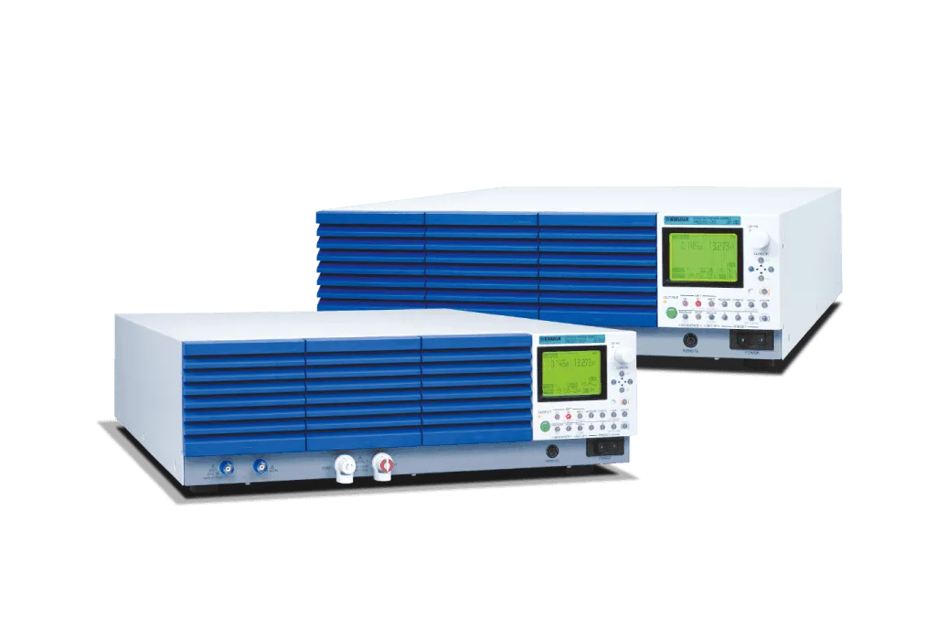


Product Overview
7 new features for optimum test simulation!
The PBZ is a series of bipolar DC programmable power supplies that can smoothly pass through zero to provide ± voltage and ± current without changing the output terminals. The PBZ is capable of 4-quadrant operation, meaning that it is capable of both sourcing and sinking power, ideal for driving both inductive and capacitive loads. This power supply comes equipped with a built-in function generator, allowing for easy waveform and sequence generation.
The output current of the PBZ can be expanded among multiple units by using the synchronization feature. The switching + linear design of the PBZ has allowed for a 40% reduction in weight (approx. 22 kg) while achieving extremely high-speed operation (CV mode: 100 kHz) and low ripple noise.
Features
Waveform generation function
Built-in function generator for customizable waveform generation!
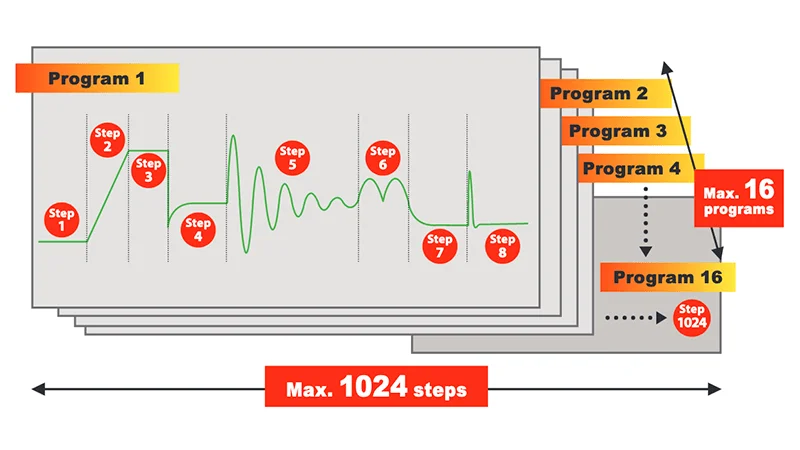
In addition to basic sine, square and triangular waveforms, the PBZ allows the operator to customize up to 16 user-defined waveforms with the internal function generator. Amplitude, frequency, start phase, frequency sweep and square wave duty can be programmed as needed. 16 user-defined waveforms can be freely edited and registered to the PBZ internal memory. The sequence feature (see P6) allows for each step in an individual waveform to be customized in detail for a maximum of 1024 steps among 16 programs. *Waveform editing requires proprietery software (Wavy for PBZ).
3 Basic Waveforms
Sine

Triangular wave

Square waves

16 User-Defined Waveforms (Default Waveforms)
Ramp
(rising)

Ramp
(falling)

Sine wave, half-cycle
(positive pole)

Sine wave, half-cycle
(negative pole)

Exponential function
(rising)

Exponential function
(falling)

Sine wave, half-wave rectification
(positive pole)

Sine wave, half-wave rectification
(negative pole)

Sine wave, full-wave rectification
(positive pole)

Sine wave, full-wave rectification
(negative pole)

Second order step response
(damping coefficient 0.1)

Second order step response
(damping coefficient 0.2)

Second order step response
(damping coefficient 0.7)

Second order impulse response
(damping coefficient 0.1)

Second order impulse response
(damping coefficient 0.2)

Second order impulse response
(damping coefficient 0.7)

Example Applications Expanded Through Waveform Generation
Power fluctuation test for automotive electronic components
Car navigation systems, others

Rechargeable battery charge/discharge test
Various rechargeable batteries

Simulated battery charge/discharge test
Digital cameras, cellular phones, and others

Constant current source for pulse plating
HDD, others

Ripple Superimposition Testing
Various electrical storage elements

DC motor durability test
Printers, others

Constant current source for magnetic field generation
Helmholtz coil

Others
- Contact resistance test for breakers and relays
- Characteristics test for solenoid valves, coils and others
Sequence function
Sequence customization for convenient waveform generation!
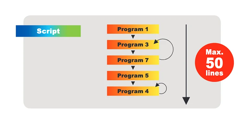
The basic sine, triangular and square waveforms (as well as the 16 user-defined waveforms) can be programmed per sequence step, allowing for easy creation of complex sequences. Sequences are composed of up to 1024 steps, which can be allocated among a maximum of 16 programs. The script function allows for multiple programs to be combined and executed as needed. As shown, Program 1 uses 8 steps, allowing for 1016 steps to be allocated among the remaining 15 programs. (1024 – 8 = 1016 steps) The script function allows the operator to specify the sequence and number of repitions for set programs. A maximum of 50 rows can be assigned to 1 script for both CV and CC mode.
Step and Program Settings
Example of Script
Synchronized operation function
Seamless sequence execution with no deviation between synchronized units!
This feature allows the user to synchronize the output of multiple PBZ units when executing a sequence, preventing any deviations from occuring even during a long sequence. *Excluding start up delay of up to 1 μs
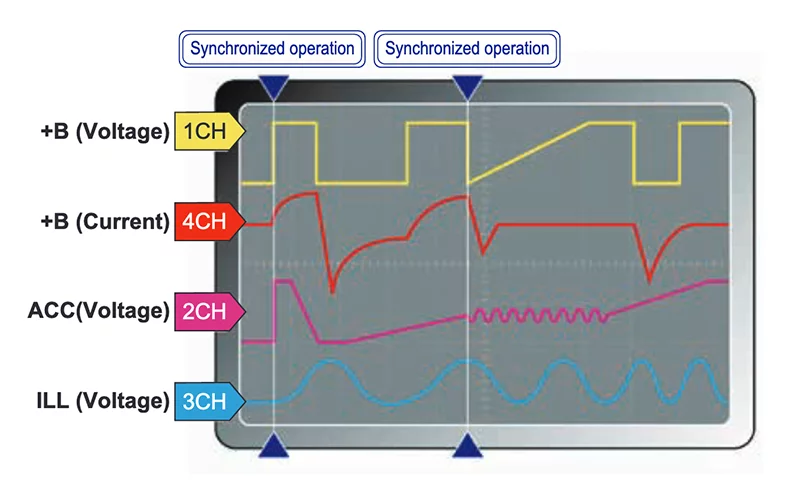
Multichannel voltage variation test example
Power for automotive vehicles is supplied by the battery, but the power is activated by multiple internal electronic components (+B→ACC→IG) turning ON/OFF in a specific order. There are an extremely large number of electronic components that can cause instability within the automobile, including engine start-up and electrical circuit chat-tering. Therefore, problems caused by this instability such as power interruptions and fluctuations can be planned for and avoided by performing rigorous voltage variation tests on all channels for automotive electronic components.
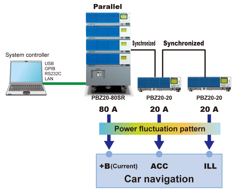
Car navigation system
- CH1: +B LINE
Power is continuously supplied from the battery to the clock and memory. - CH2: ACC LINE
The car navigation system turns ON via the ignition switch ACC contact. In this state, operations such as navigation settings and listening to music are available. - CH3: ILL LINE
+B, IG, and ACC power line (ILL) that is directly pulled up. This is a backup power line.
Parallel operation function
Easily increase capacity!
This feature allows the user to increase the output current by connecting multiple units in parallel. This setup can easily be completed with 2 identical models and the optional parallel operation kit. For systems that require more than 3 units, please refer to the PBZ-SR Series.
* For systems that require more than 3 units, please refer to the PBZ-SR Series. For systems that require more than 6 units, please contact your local Kikusui distributor. (Standard models)
Parallel operation kit (option)
The optional accessory kit for connecting 2 PBZ units in parallel (same model). Please select the following kit that best fits your testing requirements.
*Bracket is not included for PK02-PBZ and PK03-PBZ

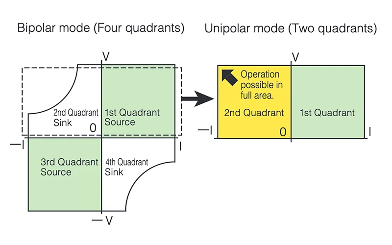
Unipolar mode
Full operation in quadrant 2
The unipolar function is unique to the PBZ. “Unipolar mode” allows the PBZ to apply current in both directions (source and sink) while current flows in a single direction. As seen in the diagram below, this feature allows the user full operation in the 1st and 2nd quadrants. Unipolar mode allows the user to bypass power restrictions (PBZ20-20: 100W, PBZ40-10: 180W) present in the 2nd and 4th quadrants when in bipolar mode.
High-speed response
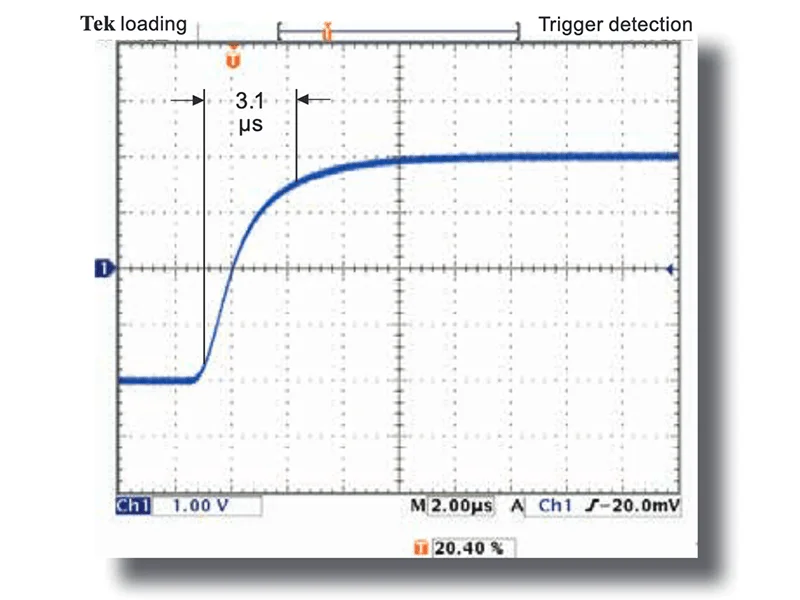
100 kHz*1 /150 kHz*2 (CV mode)
100 kHz/150 kHz frequency specifications (CV). The excellent waveform quality combined with the ultra-fast rise/fall time of 3.5 μs allow the PBZ to reproduce a wide variety of waveforms of the highest quality.
Rise time example when 3.5 μs response is set
*1 100 kHz for standard models (PBZ20-20, 40-10, 60-6.7, 80-5)
*2 Model with 150kHz_A (PBZ20-20A)
Low Ripple Noise
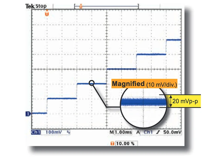
Excellent waveform quality
The excellent waveform quality of the PBZ minimizes noise effects on simulations and pulse-driven devices.
Sample of actual 0.1 V step waveform
Ripple 2 mVrms, noise 20 mVp-p (PBZ20-20)
* PBZ40-10: Ripple 4 mVrms, noise 20 mVp-p
PBZ60-6.7: Ripple 4 mVrms, noise 30 mVp-p
PBZ80-5: Ripple 4 mVrms, noise 30 mVp-p
40% lighter than previous models
The switching + linear design of the PBZ has allowed for a 40% reduction in weight (approx. 22kg) resulting in the improved accessibility and portability of bench-top test systems.
Expanded measurement
Built-in measurement features allow for easy testing without the need for multimeters and other measurement devices. Furthermore, the measurement time TRIG signal allows the operator to program measurement start time and measurement delay time.
| Setting item | |||
|---|---|---|---|
| Voltage measurement | DC | Measurement range (resolution) | 120% of rating(0.001V) |
| Accuracy *1 | ±(0.05% of reading+0.05% of rating) | ||
| AC | Measurement range (resolution) | 120% of rating/CF(0.001V) | |
| DC+AC | Measurement range (resolution) | 120% of rating(0.001V) | |
| AC and DC+AC | Accuracy*1*2 | ±(0.5% of reading + 0.1% of rating) (5 Hz to 10 kHz) | |
| ±(1% of reading + 0.2% of rating) (10 Hz to 50 kHz) | |||
| ±(2% of reading + 0.2% of rating) (50 Hz to 100 kHz) | |||
| PEAK | Measurement range (resolution) | 120% of rating(0.01V) | |
| PEAK | Accuracy *1*3 | ±(0.5% of rating) | |
| Current measurement | DC | Measurement range | 120% of rating(0.001A) |
| Accuracy *1 | ±( 0.3% of reading + 0.1% of rating) | ||
| AC | Measurement range (resolution) | 120% of rating/CF(0.001A) | |
| DC+AC | Measurement range (resolution) | 120% of rating(0.001A) | |
| AC and DC+AC | Accuracy*1*2 | ±(3% of reading + 0.1% of rating) (5 Hz to 10 kHz) | |
| ±(10% of reading + 1% of rating) (10 Hz to 100 kHz) | |||
| PEAK | Measurement range (resolution) | 120% of rating(0.01A) | |
| PEAK | Accuracy *1*3 | ±(0.5% of rating) | |
| Measurement time | 100 μs to 3600 s | ||
*1. At ambient temperature of 18 °C to 28 °C. *2. When the input signal is a sine wave with a crest factor of 3 or less within the prescribed frequency range and the measurement time is no more than 10 times the period of the input signal. *3. Peak value of a 1 kHz sine wave.
Memory function
Preset memory
Stores setting conditions most often used. Three memory slots are available for CV mode and CC mode. Settings stored are limited to DC signal and AC signal.
Setup Memory
This can be used as general memory storing all basic settings. Up to 10 memories can be set, regardless of mode.
CC/CV selection feature
Select CV mode when using constant-voltage, and CC when using constant-current. The voltage and current uppower/lower limits utilize a “V” and “I” limit function.
Response switching
Response speeds can be switched in both CV and CC mode. The output voltage and current rise/fall time will be effected by the response settings. (Response time setting indicates rise/fall time.)
| Setting description | CV mode | CC mode | |||
|---|---|---|---|---|---|
| Voltage response | Current response | ||||
| PBZ20-20 | PBZ40-10 | PBZ60-6.7 | PBZ80-5 | ||
| Selectable values | 3.5μs | 35μs | 70μs | 35μs | 35μs |
| 10μs | 100μs | 100μs | 100μs | 100μs | |
| 35μs | 350μs | 350μs | 350μs | 350μs | |
| 100μs | 1 ms | 1 ms | 1 ms | 1 ms | |
| Factory default setting | 3.5μs | 35μs | 70μs | 35μs | 35μs |
Protections (overvoltage, overcurrent, V-I LIMIT, overheating)
Overvoltage and overcurrent protection
This protection activates when the output voltage/current exceeds theprotective trip points. The protective trip points can be set seperately in both positive (+) and negative (-) polarities. The following three options can be selected when a protection is activated.
- OUTPUT-OFF: Output is turned OFF.
- POWER-OFF: Output and POWER switch are turned OFF.

- V/I-LIMIT
Suppresses voltage and Current at or more than the protection activation point. (Does not Turns the output off.)
By using the V/I-LIMIT function, the unit automatically switches from CV mode to I-LIMIT and from CC mode to V-LIMIT, allowing it to be used as a power supply that automatically transitions from CV mode to CC mode and from CC mode to CV mode.

Overheat protection
This protection is activated when the PBZ temperature reaches abnormally high levels. This protection protects the product from test environments that exceed the ambient temperature, or when sufficient ventilation has not been provided for the intake and exhaust ports.
Soft start and soft stop function
The soft start feature allows the user to gradually increase the output to a given value when turned ON. With soft stop, the user can gradually decrease the output from a given value to 0 when turned OFF. Soft start and stop times can only be set for DC settings. If the OUTPUT key is pressed while soft start or soft stop is in progress, the operation will be cancelled and output turned OFF.

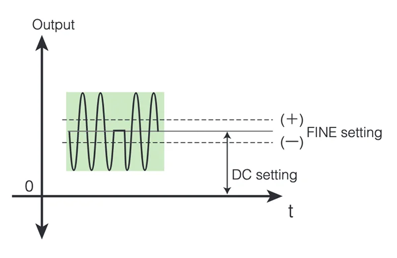
Fine settings function
Fine adjustments (increase, decrease) can be made to the DC setting value.
Input range
- PBZ20-20A/PBZ20-20
CV: DC set value ±1.0000V, Resolution 0.0001V
CC: DC set value ±1.0000A, Resolution 0.0001A - PBZ40-10
CV: DC set value ±2.0000V, Resolution 0.0001V
CC: DC set value ±0.5000A, Resolution 0.0001A - PBZ60-6.7
CV: DC set value ±3.0000V, Resolution 0.0002V
CC: DC set value ±0.3350A, Resolution 0.0001A - PBZ80-5
CV: DC set value ±4.0000V, Resolution 0.0002V
CC: DC set value ±0.2500A, Resolution 0.0001A
key lock
3 levels of key lock are available.
- Disable all key operations other than OUTPUT, RECALL, and A,B,C memory functions.
- Disable all key operations other than OUTPUT.
- Disable all key operations. (excluding KEY LOCK (SHIFT + LOCAL) KEY)
Remote sensing function
Remote sensing function stabilizes the load terminal output voltage by compensating for voltage drops caused by resistance in the load wires. This function can be used in CV mode with one-way compensation of up to approx. 0.5 V. Please make sure to select load wires with sufficient current capacity so that load wire voltage drop does not exceed the voltage compensation.
External signal input (external voltage control)
The PBZ series is compatible with two types of input signals.
- The DC signal from the internal signal source can be controlled via external voltage at the rear panel (J1 connector) from DC control signal 0 to approx. ±10 V.

- Front panel EXT SIG IN (BNC terminal) input signal.
This configuration functions as a bipolar amplifier using EXT SIG IN (BNC terminal) as the input signal. The amplifier gain, polarity (inverted or non-inverted), and offset can be configured. Maximum allowable input voltage: ±12 Vpeak. Input impedance: approx. 10 kΩ. The common terminal is connected to the COM of the OUTPUT terminal.
External signal input (external resistance control)
DC signal of the internal signal source can be controlled using an external variable resistor to change the standard voltage and voltage ratio. With CV and CC mode, the operator can control both voltage and current, respectively. The output is the sum of the external resistor setting, DC panel setting, and remote controller setting.

Interface
USB, GPIB and RS232C standard digital interface. For LAN (option), See here.
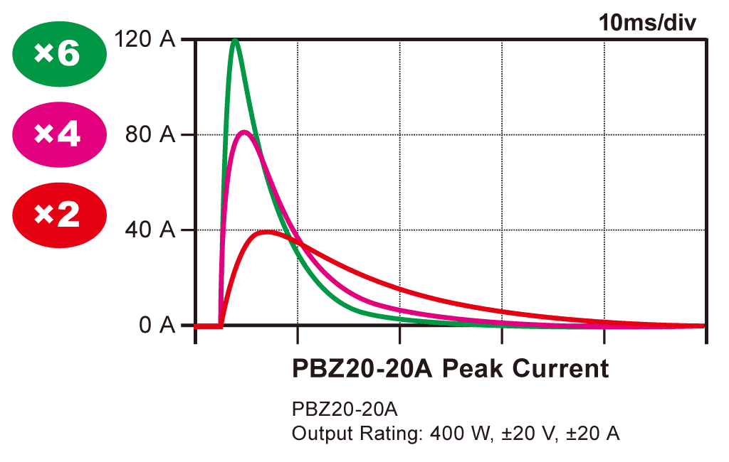
[PBZ20-20A] Peak Current output up to 6× the Rating
In CV mode, it can output short-duration peak Current up to 6× the Rating!
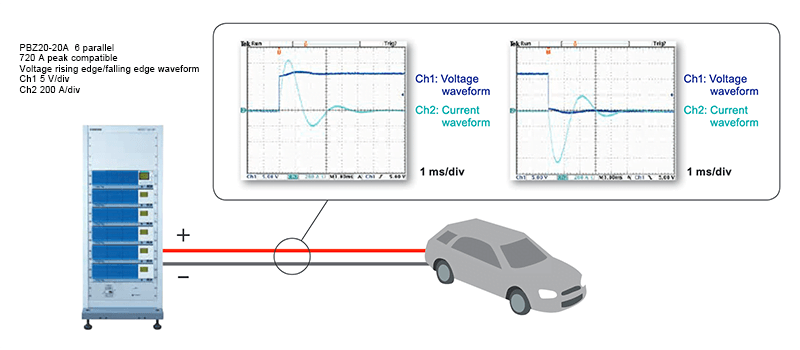
The intelligent bipolar power supply PBZ20-20A responds with high-speed performance to the requirements of power supply voltage fluctuation tests (Pulse2b, Pulse4, etc.) specified in the international standards ISO 16750-2 and ISO 7637-2, as well as the increasingly complex fluctuating waveform test requirements of individual automotive manufacturers. In addition, as the number of electrical components installed per vehicle continues to increase (with more equipment featuring large capacitor capacity), it can flexibly accommodate total Current (especially peak Current) as well.
The PBZ20-20A is capable of generating a short-term peak current up to 6 times the rating when current response is set to 1ms in CV mode.Other response settings will activate the current limit and allow the operator to safely use the device without 6x peak current output. When current response is set to 1ms, the PBZ20-20A automatically decreases response speed and allows for peak current ouput while the current limit is deactivated. This means that the current function will be active at all times when short-term peak current is not output and will have no effect on current response in CC mode. Short-term peak current output is available in both bipolar and unipolar mode.
Recommended Peak Current Duration and Range (Protection)
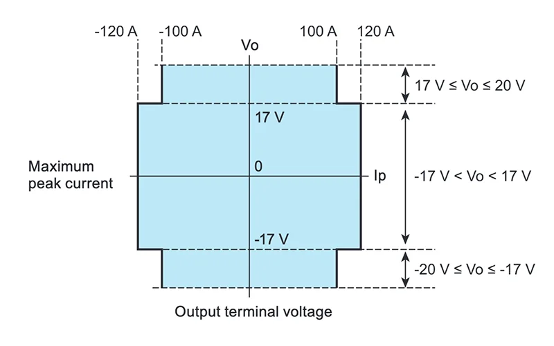
We recommend a maximum peak current output of up to 6 times the rating (5 times depending on output voltage) within a duration of 10ms (blue area on left). A minimum interval of at least 1 second is required between peak currents, as shorter intervals can cause hardware malfunction. The figure on the left shows the peak and rms current limits when the output is shorted.
- In the peak limit area, peak current is capped at 105% of 6x the rating and can be retained for at least 10 ms.
- There are cases where normal waveforms cannot be generated within the peak limit area. Current limits will still be active ensuring the safety of the operator.
- In the rms limit area, the peak current is limited by the rms value. The current will decrease down to the rated current according to the duration settings.
- When sinking power in quadrant 2 and 4, power will be limited after 10 ms and the regular current limit will be activated.

Maximum Peak Current and Terminal Voltage Output

PBZ SR Series
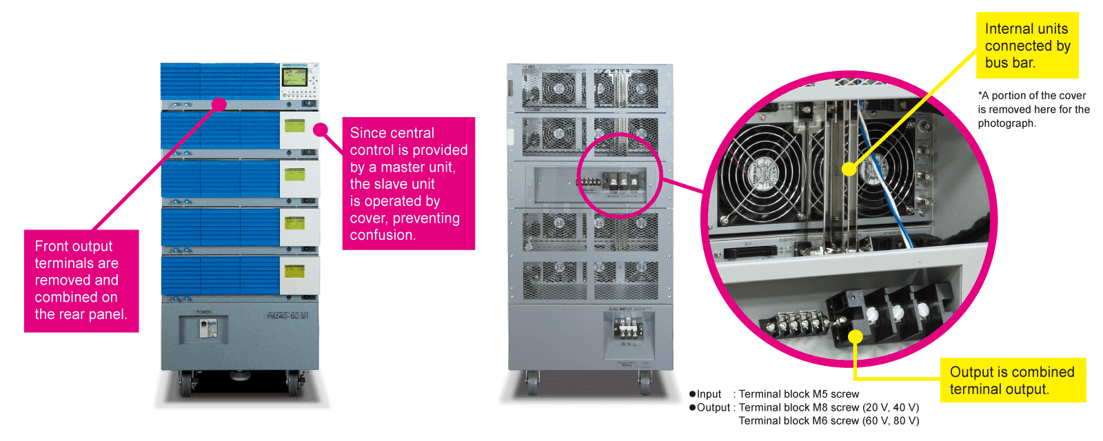
The PBZ SR series is a series of high-power bipolar DC stabilized power supplies. Based on the PBZ Intelligent Bipolar power supply series, this model supports large currents (up to ±100 A) and is assembled with exclusive rack parts (Smart Rack). 4-quadrant oper ation allows power to be supplied (source) or absorbed (sink), making this series suitable for driving inductive loads or capacitive loads. Also, LAN, USB, GPIB, and RS232C are provided (standard) as communication interfaces.
PBZ BP Series
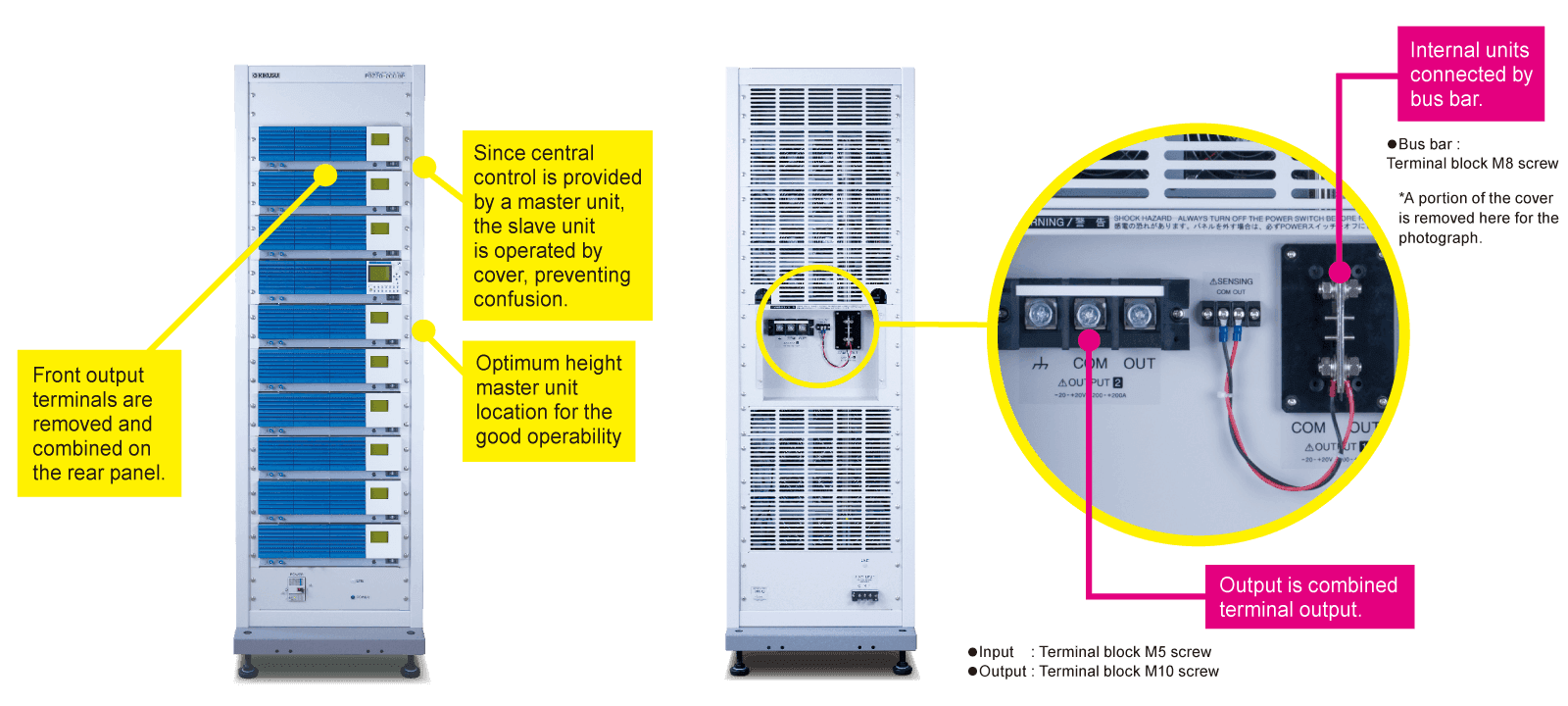
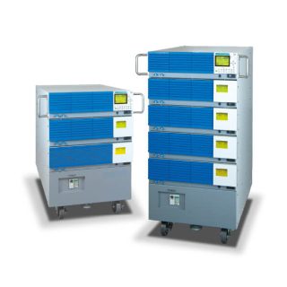
The PBZ BP series is a series of high-power bipolar DC stabilized power supplies. Based on the PBZ Intelligent Bipolar power supply series, this model supports large currents (up to ±200 A) and is assembled with rack system (bipolar pack). 4-quadrant operation allows power to be supplied (source) or absorbed (sink), making this series suitable for driving inductive loads or capacitive loads. Also, LAN, USB, GPIB, and RS232C are provided (standard) as communication interfaces.

Specifications
PBZ
| Specifications | Output | Ripple noise | Line regulation | Load regulation | AC input | |||||
|---|---|---|---|---|---|---|---|---|---|---|
| Model | CV | CC | CV | CC | CV | CC | CV | CC | Nominal Voltage | Current |
| V | A | rms/p-p | rms | mV | mA | mV | mA | V | A | |
| PBZ20-20 | ±20 | ±20 | 2 mV/20 mV(TYP) | 3mA (TYP) | ±0.005%+1 | ±0.01%+1 | ±0.005%+1 | ±0.01%+1 | 100 to 240 | 10 (max) |
| PBZ40-10 | ±40 | ±10 | 4 mV/20 mV(TYP) | |||||||
| PBZ60-6.7 | ±60 | ±6.7 | 4 mV/30 mV(TYP) | |||||||
| PBZ80-5 | ±80 | ±5 | ||||||||
PBZ20-20A
| Specifications | Output | Ripple noise | Line regulation | Load regulation | AC input | |||||
|---|---|---|---|---|---|---|---|---|---|---|
| Model | CV | CC | CV | CC | CV | CC | CV | CC | Nominal Voltage | Current |
| V | A | rms/p-p | rms | mV | mA | mV | mA | V | A | |
| PBZ20-20A | ±20 | ±20 | 2 mV/20 mV(TYP) | 3mA (TYP) | ±0.005%+1 | ±0.01%+1 | ±0.005%+1 | ±0.01%+1 | 100 to 240 | 10 (max) |
PBZ SR
Three parallel type
| Specifications | Output | Ripple noise | Line regulation | Load regulation | AC input | |||||
|---|---|---|---|---|---|---|---|---|---|---|
| Model | CV | CC | CV | CC | CV | CC | CV | CC | Nominal Voltage | Current |
| V | A | rms/p-p | rms | mV | mA | mV | mA | V | A | |
| PBZ20-60 SR | ±20 | ±60 | 3 mV/30 mV(TYP) | 5mA (TYP) | ±0.005%+1 | ±0.01%+1 | ±0.005%+1 | ±0.01%+1 | 200 to 240 Single phase | 15A (max) |
| PBZ40-30 SR | ±40 | ±30 | 6 mV/30 mV(TYP) | |||||||
| PBZ60-20.1 SR | ±60 | ±20.1 | 6 mV/40 mV(TYP) | |||||||
| PBZ80-15 SR | ±80 | ±15 | ||||||||
Four parallel type
| Specifications | Output | Ripple noise | Line regulation | Load regulation | AC input | |||||
|---|---|---|---|---|---|---|---|---|---|---|
| Model | CV | CC | CV | CC | CV | CC | CV | CC | Nominal Voltage | Current |
| V | A | rms/p-p | rms | mV | mA | mV | mA | V | A | |
| PBZ20-80 SR | ±20 | ±80 | 3 mV/30 mV(TYP) | 5mA (TYP) | ±0.005%+1 | ±0.01%+1 | ±0.005%+1 | ±0.01%+1 | 200 to 240 Single phase | 20A (max) |
| PBZ40-40 SR | ±40 | ±40 | 6 mV/30 mV(TYP) | |||||||
| PBZ60-26.8 SR | ±60 | ±26.8 | 6 mV/40 mV(TYP) | |||||||
| PBZ80-20 SR | ±80 | ±20 | ||||||||
Five parallel type
| Specifications | Output | Ripple noise | Line regulation | Load regulation | AC input | |||||
|---|---|---|---|---|---|---|---|---|---|---|
| Model | CV | CC | CV | CC | CV | CC | CV | CC | Nominal Voltage | Current |
| V | A | rms/p-p | rms | mV | mA | mV | mA | V | A | |
| PBZ20-100 SR | ±20 | ±100 | 3 mV/30 mV(TYP) | 5mA (TYP) | ±0.005%+1 | ±0.01%+1 | ±0.005%+1 | ±0.01%+1 | 200 to 240 Single phase | 25A (max) |
| PBZ40-50 SR | ±40 | ±50 | 6 mV/30 mV(TYP) | |||||||
| PBZ60-33.5 SR | ±60 | ±33.5 | 6 mV/40 mV(TYP) | |||||||
| PBZ80-25 SR | ±80 | ±25 | ||||||||
PBZ BP
Six parallel type
| Specifications | Output | Ripple noise | Line regulation | Load regulation | AC input | |||||
|---|---|---|---|---|---|---|---|---|---|---|
| Model | CV | CC | CV | CC | CV | CC | CV | CC | Nominal Voltage | Current |
| V | A | rms/p-p | rms | mV | mA | mV | mA | V | A | |
| PBZ20-120 BP | ±20 | ±120 | 6 mV / 50 mV (TYP) | 10mA (TYP) | ±0.005%+1 | ±0.01%+1 | ±0.005%+1 | ±0.01%+1 | 200 to 240 Single phase | 30 (max) |
| PBZ40-60 BP | ±40 | ±60 | 12 mV / 50 mV (TYP) | |||||||
Seven parallel type
| Specifications | Output | Ripple noise | Line regulation | Load regulation | AC input | |||||
|---|---|---|---|---|---|---|---|---|---|---|
| Model | CV | CC | CV | CC | CV | CC | CV | CC | Nominal Voltage | Current |
| V | A | rms/p-p | rms | mV | mA | mV | mA | V | A | |
| PBZ20-140 BP | ±20 | ±140 | 6 mV / 50 mV (TYP) | 10mA (TYP) | ±0.005%+1 | ±0.01%+1 | ±0.005%+1 | ±0.01%+1 | 200 to 240 Single phase | 35 (max) |
| PBZ40-70 BP | ±40 | ±70 | 12 mV / 50 mV (TYP) | |||||||
Eight parallel type
| Specifications | Output | Ripple noise | Line regulation | Load regulation | AC input | |||||
|---|---|---|---|---|---|---|---|---|---|---|
| Model | CV | CC | CV | CC | CV | CC | CV | CC | Nominal Voltage | Current |
| V | A | rms/p-p | rms | mV | mA | mV | mA | V | A | |
| PBZ20-160 BP | ±20 | ±160 | 6 mV / 50 mV (TYP) | 10mA (TYP) | ±0.005%+1 | ±0.01%+1 | ±0.005%+1 | ±0.01%+1 | 200 to 240 Single phase | 40 (max) |
| PBZ40-80 BP | ±40 | ±80 | 12 mV / 50 mV (TYP) | |||||||
Nine parallel type
| Specifications | Output | Ripple noise | Line regulation | Load regulation | AC input | |||||
|---|---|---|---|---|---|---|---|---|---|---|
| Model | CV | CC | CV | CC | CV | CC | CV | CC | Nominal Voltage | Current |
| V | A | rms/p-p | rms | mV | mA | mV | mA | V | A | |
| PBZ20-180 BP | ±20 | ±180 | 6 mV / 50 mV (TYP) | 10mA (TYP) | ±0.005%+1 | ±0.01%+1 | ±0.005%+1 | ±0.01%+1 | 200 to 240 Single phase | 45 (max) |
| PBZ40-90 BP | ±40 | ±90 | 12 mV / 50 mV (TYP) | |||||||
Ten parallel type
| Specifications | Output | Ripple noise | Line regulation | Load regulation | AC input | |||||
|---|---|---|---|---|---|---|---|---|---|---|
| Model | CV | CC | CV | CC | CV | CC | CV | CC | Nominal Voltage | Current |
| V | A | rms/p-p | rms | mV | mA | mV | mA | V | A | |
| PBZ20-200 BP | ±20 | ±200 | 6 mV / 50 mV (TYP) | 10mA (TYP) | ±0.005%+1 | ±0.01%+1 | ±0.005%+1 | ±0.01%+1 | 200 Single phase | 50 (max) |
| PBZ40-100 BP | ±40 | ±100 | 12 mV / 50 mV (TYP) | |||||||
Lineup
Options
Communication interface

M8 terminal connection kit
Parallel operation kit (for 2 units)
Vertical stand

Rack Mount Bracket

Sequence Creation Software

Resources
Product Catalog
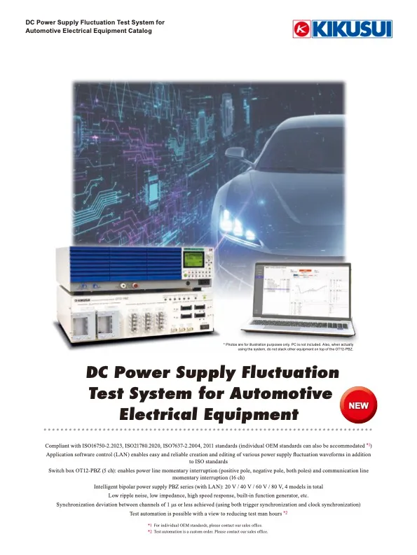
DC Power Supply Fluctuation Test System for Automotive Electrical Equipment
https://global.kikusui.co.jp/download/cat_fluctuation-test-system/
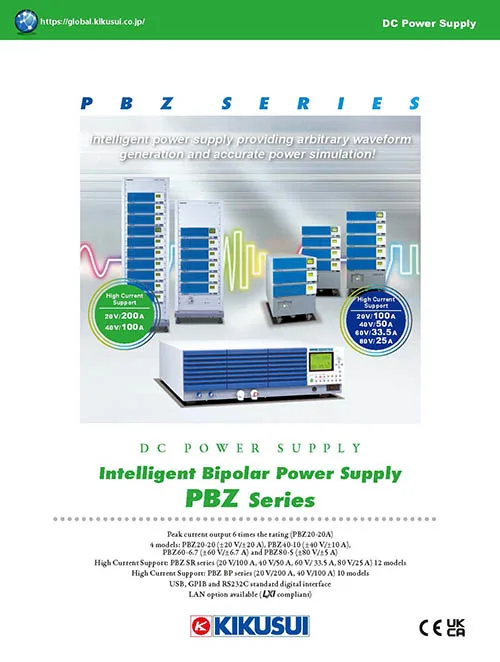
Intelligent Bipolar Power Supply - PBZSeries
https://global.kikusui.co.jp/download/cat_pbz/
Solutions
Power supply for DC motor evaluation
https://global.kikusui.co.jp/kikusui-solutions/dc-motor/

High Voltage Large Capacity Inverter Evaluation
https://global.kikusui.co.jp/kikusui-solutions/inverter/