
Compact High Voltage DC Electronic Load
PLZ-5WH2 Series
The PLZ-5WH2 high-power DC electronic load series is where durable, reliable ingenuity meets multifunctional, high-power design.Providing 5 variety of power range line-ups, from a 1 kW benchtop style model, to a high-power model that can sink up to 20 kW of power in a single unit. You can easily select the applicable power range according to the load.

Features

For evaluation of large-capacity power supplies / large-capacity storage batteries, etc!
Testing with hyper-realistic load simulation made possible!
The PLZ-5WH2 high-power DC electronic load series is where durable, reliable ingenuity meets multifunctional, high-power design.Providing 5 variety of power range line-ups, from a 1 kW benchtop style model, to a high-power model that can sink up to 20 kW of power in a single unit.
You can easily select the applicable power range according to the load. Load simulation can be achieved faster than ever before thanks to the reliable, high-speed design of the PLZ-5WH2 current control circuits. Accurate current measures can be made with extremely high-setting resolution. A color LCD display allows for highly visible, user-friendly front-panel operation. RS232C, USB, and LAN digital inter faces are included as standard for simple integration into any system.


Ideal for high capacity power supply and rechargeable battery evaluation!
Operation mode
The PLZ-5WH2 series has the following five Operation modes. In Operation mode other than +CV mode, ” UVPL* ” can be set to control Current so that the voltage does not fall below the UVP setting or less due to excessive current flow, and “UVPT” can be set to load-off. UVPL” is the “+CV mode” in the PLZ-5W series.
| Constant current (CC) mode | When a current value is specified, the current is kept at that value even when the voltage changes. |
|---|---|
| Constant resistance (CR) mode | When a conductance value is specified, the product sinks the current proportional to the voltage variation by using the value as a proportionality constant. |
| Constant voltage (CV) mode | When a voltage value is specified, the product runs the current so that the voltage is kept at that value. |
| Constant power (CP) mode | When a power value is specified, the product runs the current so that the power is kept at that value. |
| Arbitrary I-V characteristics (ARB) mode | The desired load characteristics can be set by specifying multiple arbitrary voltage values and current values as I-V characteristics. |
Arbitrary I-V Characteristics (ARB) Mode
In ARB mode, arbitrary I-V characteristics can be set by registering multiple I-V characteristic points (pairs of voltage and current values). Vales can be registered from 3 to 100, and linear interpolation is performed between the values. Minimum voltage (0.00V), current (0.00A) and the maximum viktage (1010.00V) are fixed.

Maximum Slew Rate of 20 A/μs
Rise time to Rated current is 20A/μs. Supports high-speed transient response tests, which are becoming increasingly important in power supply evaluations. In case of PLZ20005WH2

Up to 100 kW with parallel operation (Max. 5 units)
Parallel operation can be connected with a single parallel operation cable *! Flexible “high capacity” up to 5 units even with different models! (Max. 100kW, 2000A) *Needed between models to be connected. 12kW/20kW models come standard; 1kW/2kW/4kW models are optional.

Wide Ranging Operating Voltage up to 1000 V
Operating voltage ranges from 10 V to 1000 V. The minimum operating voltage required to sink current is 1.5 V.

Communication Interface
LAN (LXI)/USB/RS232C interface standard *GPIB (option)
Use a browser from a PC, smartphone, or tablet to access the web server built into the PLZ-5WH2 series for convenient control and monitoring.

Load On/Off
The following load on/off settings are available in addition to standard operations that can be carefully adjusted to fit the needs of any test environment.
- Start with “load on” when power is turned on
- Display elapsed “load on” time
- Auto “load off” when time limit is reached
- Control “load on/off” with external controls such as relays
- “Load off” by specifying conditions (Cutoff function)
Cutoff function
The cutoff function allows the user to enable “load off” once the elapsed time/voltage drop/integrated current/integrated power has been reached after “load on”. Multiple factors can be selected, with load off being implemented after the first requirement is met.
| Elapsed time | The load turns off when the elapsed time value reaches the specified value. |
|---|---|
| Voltage drop* | The load turns off when the voltmeter value reaches the specified value. |
| Integrated current | The load turns off when the ampere-hour meter value reaches the specified value. |
| Integrated power | The load turns off when the watt-hour meter value reaches the specified value. |
Changing the Response Speed
Set the response speed for CV, CR, or ARB mode according to the DUT’s conditions and application.
| Item | Description | |
|---|---|---|
| Response | Voltage | Set the response speed for CV mode: Normal, Fast |
| Conductance | Set the response speed for CR mode: Normal, Fast | |
| ARB | Set the response speed for ARB mode. The value is the filter response time. Select OFF for no filter. OFF, 500 μs, 1 ms, 2 ms, 5 ms, 10 ms, 20 ms, 50 ms, 100 ms | |
Soft start function
“Soft start” is a function that controls the rise time of the load current. “Soft start” functions only when all the following conditions are met:
- The rise time of the soft start has been set.
- “Load on” state is in constant current (CC) mode.
- When there is an input that exceeds the minimum operating condition after the load input terminal has no input.
If the load current rises sharply, the DUT output may become unstable or the DUT’s overcurrent protection circuit may be activated. In such situations, it is possible to make the load current rise slowly only when the device is activated.

| Operation mode | CC |
|---|---|
| Time setting range | 500 μs, 1 ms, 2 ms, 5 ms, 10 ms, 20 ms, 50 ms, 100 ms, or off |
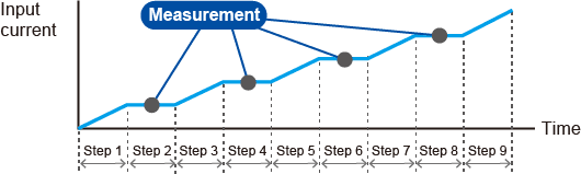
Data Logging Function
The data logging function allows the user to log measurement values (current, voltage, power) in the internal memory, and display logged data on an LCD screen (Table) as a chart (Chart). By setting measurement recording conditions, you can control the timing that measurements are recorded.

| Condition | Setting range | Description |
|---|---|---|
| Trigger | – | Set the measurement recording timing and the number of times to record measurements. |
| Source | – | Event (trigger source) that defines the measurement recording condition. Recording starts after the Initiate key is pressed and a trigger is received. |
| Immediate | Pressing Initiate applies a trigger immediately. | |
| BUS | Applies a trigger when a *TRG command is received from a PC or when the *TRG key on the front panel is pressed. | |
| DIGITAL2* | Applies a trigger when a signal is received at pin 13 of the EXT CONT connector. | |
| MSync | The triger-application timinig is synced between PLZ-5WH2 units that are synchronized. | |
| TALink | Applies a trigger when a step is executed if Generate is set to TALink in the sequence step settings | |
| Load Off | Applies a trigger when the load is turned off. | |
| Count | 1 to 65536 | The number of times to recorded measurements. |
| Delay | 0 μs to 100 s (resolution: 10 μs) | The delay time from trigger application until measurement recording. |
| Interval | Disable/ Enable | Sets whether to insert an interval between recordings when Count is 2 or higher. |
| Interval Time | 10 μs to 3600 s (resolution: 10 μs) | Recording interval time when Interval is set to Enable. |
| Sense Aperture | 10 μs to 1 s (resolution: 10 μs) | Recording time per session. The average value over time is recorded. |
*Only when Direction of Digital 2 is set to Input
Integrated Data Function
Time elapsed, integrated current and integrated power can be logged. Logging (integration) can be coordinated to start/finish when the load turns on/off or during the start or end of a sequence. Logging can also be controlled arbitrarily.
| Item | Setting range | Description |
|---|---|---|
| Integral Gate | – | Set the integrated data recording period. |
| None | Integrated data recording is started/stopped manually. | |
| Load On | Recording is started/stopped automatically in synchronization with load on/load off. Or, recording is started or stopped manually. | |
| Program Run | Recording is started/stopped automatically in synchronization with sequence execution start/stop. Or, recording is started or stopped manually. | |
| Reset | – | Selects the integrated data reset method. If the unit is restarted, integrated data is reset. |
| Manual | Integrated data is reset when the “Reset” key is pressed. | |
| Auto | Integrated data is automatically reset before the start of recordings. Or, integrated data is reset when the “Reset” key is pressed. |

Saving Measurement Data
Measurement data can be stored in CSV format to a USB memory device.
Reproduce the load as you imagine it.
Testing with hyper-realistic load simulation made possible!
Pulse function
Pulse function refers to the operation of executing two settings repetitively. It is suitable for transient response characteristics testing of large capacity power supplies and batteries. When the pulse operation is in progress, a trigger signal is output from the TRIG OUT connector on the front panel. You can set this regardless of whether the load is on or off. This function operates in CC and CR modes. The pulse amplitude is set with a value or a percentage of the load value.

When the pulse operation is in progress, a trigger signal is output for 10 μs from the TRIG OUT connector on the front panel when the current amplitude changes from low (Depth) to high (Set) level.

| Operation mode | CC and CR | |
|---|---|---|
| Frequency setting range | 1.0 Hz to 10.0 kHz | |
| Frequency setting resolution* | 1 Hz to 10 Hz | 0.1Hz |
| 11Hz to 100 Hz | 1Hz | |
| 110Hz to 1000 Hz | 10Hz | |
| 1.1kHz to 10.0 kHz | 0.1kHz | |
Sine Function
The sine function varies the current sinusoidally. It is suitable for superposed ripple testing of large capacity power supplies and batteries. When a sine operation is in progress, a trigger signal is output from the TRIG OUT connector on the front panel. You can set this regardless of whether the load is on or off. This function operates in CC mode. You cannot set the slew rate. Set the sine amplitude with a value.

When a sine operation is in progress, a trigger signal is output for 10 μs from the TRIG OUT connector on the front panel when the current passes through the Set value on the rising edge (sine wave phase at 0 degrees).

| Operation mode | CC | |
|---|---|---|
| Frequency setting range | 1 Hz to 1 kHz, 2 kHz, 5 kHz, 10 kHz | |
| Frequency setting resolution* | 1 Hz to 10 Hz | 1Hz |
| 20 Hz to 100 Hz | 10Hz | |
| 200 Hz to 1000 Hz | 100 Hz | |
| 1000 Hz to | 2 kHz, 5 kHz, 10 kHz | |
Sequence function
A sequence consists of programs and steps. A program is a collection of steps. Steps are executed in order one at a time, starting from step 1. The completion of the last step signifies that the program has been executed once. When the specified number of program loops is completed, the sequence ends. You can set the load state (load on or off, load value, slew rate) at the end of the sequence of a program.

| Setting range | Setting item | Description |
|---|---|---|
| By step | Load value | Current, conductance, voltage, power. The values that can be set depend on the current operation mode. |
| Slew rate | Sets the speed of change when the current is changed. | |
| Step execution time | 0.000050 s to 3600000 s (50 μs to 1000 h), resolution: 1 μs | |
| Load on/off control | To turn the load on, set the load setting transition method to step or ramp. | |
| Others | Trigger signal setting, trigger signal output | |
| For each program | Number of loops of program | 1 to 100000 repetitions, or infinite repetitions. |
| Protection functions | Specifies the value at which a protection function (OCP, OPP, UVP) is activated. |
TALink
The TALink (Transient Acquire Link) trigger makes it possible to log data in PLZ-5WH2 in synchronization with the sequence steps. Logged data can then be accessed through communication with the PLZ-5WH2 and saved to a USB as a CSV file.
Alarm Function
This function detects anomalies and protects the DUT. There are two types of alarm based on the urgency level: alarm 1 (high urgency) and alarm 2 (low urgency).
Alarm 1 (high urgency)
| Name | Operation |
|---|---|
| Overvoltage detection (OVP) | Load off |
| Reverse-connection detection (Reverse) | |
| Overheat detection, overcurrent detection of the front-panel DC INPUT terminals (OTP/Front) | |
| Alarm input detection (External) | |
| Parallel operation anomaly detection |
Alarm 2 (low urgency)
| Name | Mode | Operation |
|---|---|---|
| Overcurrent protection (OCP) | CR, CV, CP | Load off or limit |
| Overpower protection (OPP) | CC, CR, CV, ARB | |
| Undervoltage protection (UVP) | CC, CR, CP, ARB | Load off, limit, or activation off |
| Watchdog protection (WDP) | All | Load off |
This function limits the current (UVPL) or turns off the load (UVPT) when the voltage applied to the product becomes equal to or less than the UVP setting. You can set this regardless of whether the load is on or off.
| Trip | Turns the load off. The setting display changes to UVPT. |
|---|---|
| Limit | Limits the voltage so as not to become equal to or less than the set value. The setting display changes to UVPL. |
ABC Preset Memories
Three setting values can be stored in preset memory slots A, B, and C. All saved settings can be accessed at the press of a button, which is perfect for when you want to quickly switch between three sets of values.
Setup Memory
The setup memory can store up to 20 sets (0 to 19) of the current conditions of the items listed below. The current conditions can also be saved in a USB memory device.
- Operation mode
- Load values (current, voltage, conductance, power)
- Slew rate
- Pulse amplitude (current/conductance or percentage)
- Pulse interval (frequency/time of one cycle and duty cycle/operating time on the high side)
- Sine amplitude (current)
- Sine frequency
- Alarm operating conditions
- Content of ABC preset memories
A file saved on the PLZ-5WH2 can be transferred to the PLZ-5W via a USB memory device. If the UVP is set to “limit” on the PLZ-5WH2, this will be changed to +CV mode on the PLZ-5W (PLZ205W, PLZ405W, PLZ1205W).
External control
PLZ-5WH2 can be controlled/monitored from an external device.
The external control terminals are isolated from the load inputterminal.

| Terminal No. | In/Out *1 | Signal name | Description |
| 1 | – | STATUS COM | Status signal common for pins 14 to 16. |
| 2 | NC | – | – |
| 3 | NC | – | – |
| 4 | NC | – | – |
| 5 | IN | ALARM CLEAR | Alarm clearing input |
| 6 | IN | ALARM IN | Alarm input |
| 7 | NC | – | – |
| 8 | NC | – | – |
| 9 | IN | TRIG INPUT | Trigger input. Resumes program execution if Wait(post) was set to Trig IN in a sequence step and the program was paused. |
| 10 | – | A COM | This is connected to the chassis. |
| 11 | OUT | DIGITAL 0 | DIGITAL0 output. Sequence control possible. |
| 12 | OUT | DIGITAL 1 | DIGITAL1 output. Sequence control possible. |
| 13 | IN/OUT | DIGITAL 2 | DIGITAL2 I/O. Input/output switchable. Sequence signal output or the trigger input of sequences and measurement function. |
| 14 | OUT | ALARM1 | ALARM1 output. ON when overvoltage detection, reverse-connection detection, overheat detection, alarm input detection, or parallel operation anomaly detection is activated, and also during external alarm input. |
| 15 | OUT | ALARM2 | ALARM2 output. ON during OCP, OPP, UVP, or WDP operation. |
| 16 | OUT | LOAD ON STATUS | Load-on status output. ON during load on. |
| 17 | NC | – | – |
| 18 | IN | LOAD ON / OFF CONT | Load on/off control input. Logic level switchable. |
| 19 | – | A COM | This is connected to the chassis. |
| 20 | IN | EXT CONT ADD | External voltage control input. Controls the load setting of CC mode by adding current. |
| 21 | IN | EXT CONT MODE | External voltage control input. Controls the load values of CC, CR, and CP modes. |
| 22 | IN | EXT CONT CV | External voltage control input. Controls the voltage of CV mode. |
| 23 | – | A COM | This is connected to the chassis. |
| 24 | OUT | IMON | Current monitor output. |
| 25 | NC | – | – |
*1 1000 V reinforced insulation between each terminal and the DC INPUT terminal.
Current and Voltage Monitor
In addition to the conventional current monitor output, voltage monitor output (0 V to 10 V/Output of 1/100 of measured voltage) has been added to the front BNC connector.

USB Keyboard
When a keyboard is connected to the USB connector on the front panel, numbers/characters can be entered from the keyboard.
The types of keyboards that you can use are 101-key and 104-key keyboards.

Synchronized operation function
The following synchronization features are available when simply connecting the PLZ-5WH2 with other equipment using a communication cable. Any of the models in the PLZ-5WH2 series can be connected together. Synchronized operation is possible even during parallel operation.
- Synchronizing load on/off among multiple pieces of equipment.
- Synchronizing measurements.
- Synchronizing the start time and resume time for sequences across multiple units.

Remote sensing function
With remote sensing, the voltage measurement point can be changed from the load input terminal to the DUT sensing point. By connecting the sensing leads to the DUT, the effects of voltage drops caused by resistance in the load cables can be reduced and the operation in CR / CV / CP / ARB mode stabilized.
- Remote sensing input rated voltage: 1000 V
Applications
Battery Discharge Testing
Battery discharge testing and storage of results can be performed without a PC.
The acquired data can be saved in CSV format on USB memory.

EV Charger Aging Tests
LV124 Standard L-02 Life test – high-temperature endurance test (Durability – Heat) [Life test]
Combination of AC power source and electronic load equipment

DC-DC Converter Evaluation
DC-DC converter performance tests vital for automotive electric components can easily be carried out by controlling the converter input (DC power supply) and output (DC electronic load). The DC power supply and electronic load can be started up simultaneously for variation tests and efficiency tests.

Specifications
Specifications
| Specifications | Rating | Constant current (CC) mode | Constant voltage (CV) mode | Constant resistance (CR) mode | Constant power (CP) mode | Power consumption | |||||||||||
|---|---|---|---|---|---|---|---|---|---|---|---|---|---|---|---|---|---|
| Model | Operating voltage | Current | Power | Operating range | Setting range | Resolution | Operating range | Setting range | Resolution | Operating range * | Setting range | Operating range | Setting range | Resolution | |||
| Range H | Range L | Range H | Range L | ||||||||||||||
| PLZ1005WH2 | 10 to 1000 V | 20 A | 1000 W | 0 to 20 A | 0 to 20.2000 A | 0.0005 A | 10 to 1000 V | 0 to 1010.00 V | 0.02 V | 500mS to 0S | 5mS to 0S | 505.00mS to 0.00S | 5.05000mS to 0.00000S | 0 to 1000 W | 0 to 1010.00 W | 0.02 W | 70 VAmax |
| PLZ2005WH2 | 40 A | 2000 W | 0 to 40 A | 0 to 40.400 A | 0.001 A | 1S to 0S | 10mS to 0S | 1.01000S to 0.00000S | 10.1000mS to 0.0000S | 0 to 2000 W | 0 to 2020.00 W | 0.05 W | 90 VAmax | ||||
| PLZ4005WH2 | 80 A | 4000 W | 0 to 80 A | 0 to 80.800 A | 0.002 A | 2S to 0S | 20mS to 0S | 2.02000S to 0.00000S | 20.2000mS to 0.0000S | 0 to 4000 W | 0 to 4040.0 W | 0.1 W | 150 VAmax | ||||
| PLZ12005WH2 | 240 A | 12000 W | 0 to 240 A | 0 to 242.40 A | 0.005 A | 6S to 0S | 60mS to 0S | 6.0600S to 0.0000S | 60.600mS to 0.000S | 0 to 12000 W | 0 to 12.1200 kW | 0.0005 kW (0.5) | 360 VAmax | ||||
| PLZ20005WH2 | 400 A | 20000 W | 0 to 400 A | 0 to 404 A | 0.01 A | 10S to 0S | 100mS to 0S | 10.1000S to 0.0000S | 101.000mS to 0.000S | 0 to 20000 W | 0 to 20.2000 kW | 590 VAmax | |||||
*1. Conductance [S] = input current [A]/input voltage [V] = 1/resistance [Ω]
Line-up

Options
GPIB Converter

Parallel Operation Signal Cable Kit


High-Voltage Load Cable

Sequence creation and control software “Wavy”

Rack Mount Brackets
For PLZ1005WH2, PLZ2005WH2, PLZ4005WH2
For PLZ12005WH2
For PLZ20005WH2

