Slim Wide Range Variable Switching Power Supply PWX Series
A next-generation, internet-enabled rack mounted power supply

Features


Ideal for N-to-M network-based remote control and monitoring. A Next-Generation Rack-Mounted Power Supply
The PWX series is a CV/CC programmable regulated DC power supply optimally designed for rack-mounted operation. To increase its mounting efficiency, it has a 19-inch rack width with a thin shape and intakes and outtakes for cooling on only the front and back surfaces so that it can be mounted flush top and bottom.
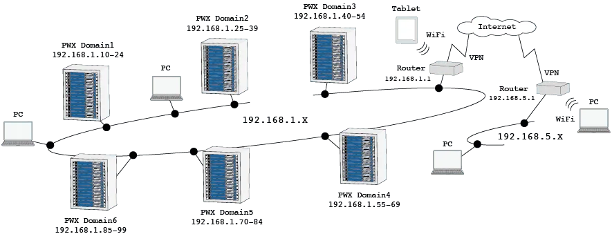
Furthermore, this series is equipped with essential communication interfaces for system upgrades, including LAN, USB, and RS232C as standard. By utilizing the VMCB (Virtual Multichannel Bus) function*, efficient remote control and monitoring of 1-to-N, N-to-M, and large-scale network types can be achieved. LAN communication allows control and monitoring from web browsers on PCs, smartphones, and tablets. Additionally, it is certified for LXI (LAN eXtensions for Instrumentation), making it easy to configure when connecting to measurement systems via LAN. Remote management of power supplies located in separate buildings can also be easily realized.
The output specifications include two types of output power: 750W and 1500W, with a wide range of voltage and current settings possible in a “3:1” power type. For example, the PWX1500ML with a rated output power of 1500W allows seamless operation from 80V-18.75A to 26.8V-56A. The input power voltage is also a universal specification of 85V to 265V, with a built-in PFC (Power Factor Correction) circuit to suppress harmonic current. Other features include analog external control and monitor output, master-slave parallel operation function, various protection functions, memory functions, etc. *Supported from Half-Rack Model Ver2.0
Equipped with standard LAN interface and VMCB (Virtual Multi-Channel Bus) function
to support network-based remote control and monitoring
The PWX series is equipped with LAN, USB, and RS232C interfacesas standard features. By using the feature of virtual multi-channelbus (VMCB)*1, it allows you to control remotely and monitoringfor 1-to-N as well as N-to-M for large-scale networks.
In particular,the LAN interface is LXI compliant, enabling you to easily controland monitor the power supply through a browser on a PC, smartphone,or tablet by accessing the web server built into the PWXseries.
Additionally, the optional application software, Wavy forPWX (SD013-PWX), sequence creation and control software,allows you to change settings for specific channels (in individual)on VMCB-connected PWX series power supplies, and lets youperform batch control using global commands*2. You can alsoturn the output ON and OFF on multiple units and adjust theoutput voltage and current.
*1: This function for the PWX750ML applies to the firmware version 2.0 and later. *2: This is only enabled for “Direct control” on Wavy for PWX. Global commands that can be also used under control with VXI-11, HiSLIP, and SCPI-RAW.
Basic configuration with LAN interface and VMCB (example)
As shown in the figure below, it is possible to connect a PC and the PWX series with a hub to create a virtual group using a LAN connection. A maximum of 255 virtual groups can be set, and the maximum number of units can be configured up to 31 units per group. A group can have a mixture of models.

| configuration | IP address | domain number | channel number |
|---|---|---|---|
| master machine | 192.168.1.1 | 1 | 0 |
| Slave unit | 192.168.1.2* (*) | 1 | 1 |
| 192.168.1.3* (*) | 1 | 2 |
Automatic setting by DHCP server is also acceptable.
Communication Monitoring function :
It is equipped with a function to monitor communication. For example, if the LAN cable is disconnected and communication is not established within the set time, an alarm (alarm lamp lights up) will be triggered, and the output will be turned off. This prevents operation in an uncontrolled state and enhances system reliability. *Supported from Firmware Ver.2.2× or more
Security for LAN connectionsAccess to the built-in web server can be restricted with a password. Also, when using VXI-11, HiSLIP, and SCPI-RAW for control, host restrictions can be set with the IP address. It is possible to prevent access from any terminal other than the ones registered as a host (up to 4 hosts can be registered).
LAN Interface
It is characterized by its ability to control a large number of devices at high speed, with a theoretical maximum controllable number of approximately 4.2 billion (the maximum communication speed varies depending on the number of connected devices). Additionally, due to its standard, it is possible to mix the controlling side (controller) and the controlled side, allowing for various applications. Furthermore, in computer systems with Apple Bonjour installed, access can be made using host names instead of IP addresses. Equipped with AUTO MDIX function: The PWX series can automatically determine whether the connected LAN cable is straight or cross and connect in the appropriate manner.

USB Interface
The USB interface has a feature of high versatility, and the ease of a setup. The automatic recognition by the plug and play releases a user from the complex setting operation under the digital control, and it can be suitable interface when control by 1:1. In accordance with the standard, the maximum number of the connected devices can be configured up to 127 units. Moreover, the USB interface of the PWX series complies to USB2.0, and it has realized transmission speed of a maximum of 12 Mbps (es) (Full Speed).

Easy access with embedded web server
Use a browser from a PC, smartphone, or tablet to access the web server built into the PWX series for convenient control and monitoring.

Application Software
The software that supports to the auto testing of the power supply. Allows you to create and edit sequence data easily using a mouse !
SD013-PWX (Wavy for PWX) is an application software that supports sequence creation and the operation for Kikusui power supplies and electronic loads. Wavy allows you to create and edit sequences visually with a mouse without programming knowledge. It enables you to control the power supply in much the same way as remote controller for such monitoring the voltage and current, logging and so on.

RS232C Interface
The PWX series is also equipped with a RS232C connector. It can be used for communication with PCs and sequencers. Since the PWX series has a RJ45 connector, it is required for a separate D-sub 9PRJ45 adapter cable (RD-8P/9P).

Emulation setting
Command language setting function
Emulate devices from companies around the world!
The command language and the emulation which are used at the time of remote control can be set. When the emulation setting is selected, the digital remote control is possible as a substitute of other manufacturer’s device. Furthermore, the RS232C interface corresponds to other products by setting the command language into a LGCy language.
Operating Range
3 times output power rating
A wide range of voltage and current settings can be combined within its output power rating (3 times). For example, the output power of 1500 W model, the PWX1500ML is capable to operate seamlessly from the range of “80 V-18.75 A” to “26.8 V-56 A”.

| Model Type | Rated voltage range | Example of Output rating voltage | 750W | 1500W | ||
|---|---|---|---|---|---|---|
| L (LF) | 10V to 30V | 10V | 75A to 25A | 75A | 150A to 50A | 150A |
| 12.5V | 60A | 120A | ||||
| 15V | 50A | 100A | ||||
| 20V | 37.5A | 75A | ||||
| 30V | 25A | 50A | ||||
| ML (MLF) | 26.8V to 80V | 26.8V | 28A to 9.37A | 28A | 56A to 18.75A | 56A |
| 30V | 25A | 50A | ||||
| 35V | 21.4A | 42.8A | ||||
| 40V | 18.75A | 37.5A | ||||
| 45V | 16.66A | 33.33A | ||||
| 60V | 12.5A | 25A | ||||
| 80V | 9.375A | 18.75A | ||||
| MH (MHF) | 75V to 230V | 75V | 10A to 3.26A | 10A | 20A to 6.52A | 20A |
| 80V | 9.375A | 18.75A | ||||
| 100V | 7.5A | 15A | ||||
| 150V | 5A | 10A | ||||
| 200V | 3.75A | 7.5A | ||||
| 230V | 3.26A | 6.52A | ||||
| H (HF) | 214.2V to 650V | 214.2V | 3.5A to 1.153A | 3.5A | 7A to 2.307A | 7A |
| 300V | 2.5A | 5A | ||||
| 400V | 1.875A | 3.75A | ||||
| 500V | 1.5A | three a (baseball) | ||||
| 600V | 1.25A | 2.5A | ||||
| 650V | 1.153A | 2.307A | ||||
Space Comparison
This product replaces multiple single-range units!

Comparison of PWR1600L and PWX1500L

Capacity Expansion
Series operation
You can connect up to two units in series. The total of the output voltages of the two units is applied to the load. The voltage setting accuracy is the same as the accuracy of an individual unit.
*You cannot perform master-slave configuration in series operation. *Excluding the PWX750HF and the PWX1500H.
Practical convenient functions are equipped as standard features.
Bleeder on/off function
The capacitor is connected to the output terminal of the PWX series, and the bleeder circuit is equipped to discharge the electric charge when the OUTPUT is OFF. For example, when the battery is connected to the output terminal, even if it is in the state of OUTPUT OFF, when the bleeder circuit is set to ON, the bleeder circuit will discharge electric charges of the battery. In this case, excessive electric discharge can be prevented by setting the bleeder circuit to OFF state. It is possible to omit the diode for reverse current prevention required for the charge of such a battery.
Rise state setting when output is on
You can set for the priority operation mode (CC (constant current) priority/CV (constant voltage) ) when the output is turned ON. It prevents the overshooting when the output is turned ON.
Preset memory function
The preset memory function allows you to save up to three combination of each preset value of voltage, current, OVP, OCP, and UVL. The saved preset value can be called from the preset memory on the front panel.
Master-slave parallel operation
In master-slave parallel operation, one unit is the master unit, and all other units connected in parallel are slave units. The master and slave units must all be the same model. You can control the whole system by operating the master. You can use master-slave parallel operation to increase the output current (maximum output current: the rated output current of one unit × the number of units connected in parallel). You can connect up to four units, including the master, in parallel. The dif ference in the output voltage and output current between the master unit and the slave u n i t s i s w i t h i n approximately 5 % of the rating.

Analog Interface
The PWX series is equipped with external voltage/resistance control, which are interfaces necessary for analog external control and monitoring applications for test power supply devices. The input external signal and the output status signal can be conducted through the J1 connector on the rear panel.


Isolated Analog Interface (factory option)
The optional isolated analog interface can be installed upon request at the time of an order. You can use a signal that is isolated from the reference potential of the PWX to control the output voltage/ current, turning output on/off, and output shut down control using an external contact, and output voltage/current monitoring. This option can be selected from the voltage control type (0 V to 5 V or 0 V to 10 V) or the current control type (4 mA to 20 mA).
Front Panel

Rear Panel

Solution for the Environment, New Energy FieldVariable Internal Resistance Feature*Factory option
Variable Internal Resistance Feature
The variable internal resistance feature enables you to easily simulate the internal resistance of rechargeable batteries, solar batteries, fuel cells, and the like. By setting the internal resistance value in constant voltage (CV) mode, you can decrease the output voltage according to the output current. You can use a CONFIG setting to set the internal resistance.
Variable range
Rint : Internal resistance
0 <Rint ≦ Rint (max)
| PWX750LF | PWX750MLF | PWX750MHF | PWX750HF | PWX1500L | PWX1500ML | PWX1500MH | PWX1500H | |
|---|---|---|---|---|---|---|---|---|
| Rint (min) [Ω] | 0.0001 *1 | 0.001 | 0.01 | 0.1 | 0.0001 | 0.001 | 0.01 | 0.1 |
| Rint (max) [Ω] | 0.4000 *1 | 2.857 | 23.00 | 185.7 | 0.2000 *1 | 1.429 | 11.50 | 92.9 |
| Resolution [Ω] | 0.0001 *1 | 0.001 | 0.01 | 0.1 | 0.0001 *1 | 0.001 | 0.01 | 0.1 |
*1 When the value is set from the front panel, the least significant digit is not shown on the panel display. The value varies at a higher resolution than what is hown, and the least significant digit is rounded and shown in the next higher digit.
The maximum internal resistance that can be set from the front panel during parallel operation is the value obtained by dividing Rint (max) during standalone operation by the number of units in parallel operation. The resolution is the value obtained by dividing the resolution during standalone operation by the number of units in parallel operation.
Specifications
| PWX750LF | PWX750MLF | PWX750MHF | PWX750HF | PWX1500L | PWX1500ML | PWX1500MH | PWX1500H | |
|---|---|---|---|---|---|---|---|---|
| Maximum internal resistance that can be set Rint(max)[Ω] | 0.400 | 2.857 | 23.00 | 185.7 | 0.200 | 1.429 | 11.50 | 92.9 |
Specifications
PWX Series 750W model
AC input
| Item/Model | PWX750LF | PWX750MLF | PWX750MHF | PWX750HF | |
|---|---|---|---|---|---|
| Half rack size | PWX750ML | ||||
| Nominal input rating | 100 Vac to 240 Vac, 50 Hz to 60 Hz, single phase | ||||
| Input voltage range | 85 Vac to 265 Vac | ||||
| Input frequency range | 47 Hz to 63 Hz | ||||
| Current (MAX) *1 | 100 Vac | 10.5A | |||
| 200 Vac | 5.25A | ||||
| Inrush current *2 | 70 A or less | ||||
| Power (MAX) *3 | 1100VA | ||||
| Power factor (TYP) *1 | 0.99 (input voltage 100 V), 0.97 (input voltage 200 V) | 0.98 (input voltage 100 V), 0.96 (input voltage 200 V) | |||
| Efficiency *1 | 74 % or greater | ||||
| Hold-up time for power interruption *3 | 20 ms or greater | ||||
*1. With rated load. *2. Excludes the charge current component that flows through the capacitor of the internal EMC filter circuit immediately after the POWER switch is turned on (for approximately 1 ms). *3. 100 Vac with rated load.
Output
| Item/Model | PWX750LF | PWX750MLF | PWX750MHF | PWX750HF | ||
|---|---|---|---|---|---|---|
| Half rack size | PWX750ML | |||||
| Rating | Output voltage *1 | 30V | 80V | 230V | 650V | |
| Output current *1 | 75A | 28A | 10A | 3.5A | ||
| Output power | 750W | |||||
| Voltage | Setting range | 0V to 31.5V | 0V to 84V | 0V to 241.5V | 0V to 682.5V | |
| Setting accuracy | ±(0.05%of set+0.05% of rtg) | |||||
| Line regulation *2 | ±5mV | ±10mV | ±25mV | ±67mV | ||
| Load regulation *3 | ±5mV | ±10mV | ±25mV | ±67mV | ||
| Transient response *4 | 1 ms or less | 7 ms or less | ||||
| Ripple noise *5 | (p-p)*6 | 60mV | 80mV | 120mV | 330mV | |
| (rms) *7 | 8mV | 8mV | 25mV | 60mV | ||
| Rise time | Rated load | 100ms | ||||
| No load | 100ms | |||||
| Fall time *8 | Rated load | 100ms | 150ms | 250ms | ||
| No load | 450ms | 550ms | 1500ms | 3000ms | ||
| Maximum remote sensing compensation voltage (single line) | 1.5V | 4V | 5V | 5V | ||
| Temperature coefficient (MAX) *9 | 100 ppm/°C (during external control) | |||||
| Current | Setting range | 0A to 78.75A | 0A to 29.4A | 0A to 10.5A | 0A to 3.675A | |
| Setting accuracy *10 | ±(0.5%of set+0.1% of rtg) | |||||
| Line regulation | ±9.5mA | ±4.8mA | ±3mA | ±2.35mA | ||
| Load regulation | ±20mA | ±10.6mA | ±7mA | ±5.7mA | ||
| Ripple noise *11 | (rms) *7 | 150mA | 65mA | 30mA | 15mA | |
| Temperature coefficient (TYP) *9 | 100 ppm/°C | |||||
*1. The maximum output voltage and current are limited by the maximum output power. *2. 85 Vac to 135 Vac or 170 Vac to 265 Vac, fixed load. *3. The amount of change that occurs when the load is changed from no load to rated load (rated output power/rated output voltage) with rated output voltage. The value is measured at the sensing point. *4. The amount of time required for the output voltage to return to a value within “rated output voltage ± (0.1 % + 10 mV).” The load current fluctuation is 50 % to 100 % of the maximum current with the set output voltage. *5. Measured using an RC-9131 1:1 probe that conforms to the JEITA specifications. At the rated output current. *6. When the measurement frequency bandwidth is 10 Hz to 20 MHz. *7. When the measurement frequency bandwidth is 5 Hz to 1 MHz. *8.When the breeder circuit on/off setting is on. *9. When the ambient temperature is within 0 °C and 50 °C. *10. When the output voltage (Rated Power ÷ Rated Current) is 10 % to 100 % of the rating. At the rated output current.
Display function
| Item/Model | PWX750LF | PWX750MLF | PWX750MHF | PWX750HF | |
|---|---|---|---|---|---|
| Half rack size | PWX750ML | ||||
| Voltage display | Maximum display | 99.99 (fixed decimal point) | 999.9 (fixed decimal point) | ||
| Display accuracy | ±(0.2 % of rdng +5 digits) | ||||
| Current display | Maximum display | 99.99 (fixed decimal point) | 9.999 (fixed decimal point) | ||
| Display accuracy | ±(0.5 % of rdng +5 digits) | ||||
| Power display *1 | The PWR DSPL LED lights in red. | ||||
| Maximum display | 9999 | ||||
| Display accuracy | Displays the result of multiplying the current and voltage | ||||
| Operation display | OUTPUT ON/OFF, CV operation, CC operation,Alarm operation, Remote operation (LAN operation),Key lock operation, Preset memory | ||||
*1. Press PWR DSPL to display the power on the ammeter. Each time you press this key, the display switches between power and current.
Protection functions
| Item/Model | PWX750LF | PWX750MLF | PWX750MHF | PWX750HF |
|---|---|---|---|---|
| Half rack size | PWX750ML | |||
| Protection functions | Overvoltage protection (OVP), Overvoltage protection 2 (OVP2), Overcurrent protection (OCP), Undervoltage limit (UVL), Overheat protection (OHP), Overheat protection 2 (OHP2), Fan failure protection (FAN), Incorrect sensing connection protection (SENSE), Low AC input protection (AC-FAIL), Shutdown (SD), Power limit (POWER LIMIT), Communication monitoring (WATCHDOG) | |||
Signal output
| Item/Model | PWX750LF | PWX750MLF | PWX750MHF | PWX750HF | |
|---|---|---|---|---|---|
| Half rack size | PWX750ML | ||||
| Monitor signal output *1 | Voltage monitor (VMON) | Selectable monitor voltage range: 0 V to 5 V or 0 V to 10 V | |||
| Setting accuracy | 2.5 % of rtg | ||||
| Current monitor (IMON) | Selectable monitor voltage range: 0 V to 5 V or 0 V to 10 V | ||||
| Setting accuracy | 2.5 % of rtg | ||||
| Status signal output *1 *2 | OUTON STATUS, CV STATUS, CC STATUS, ALM STATUS, PWR ON STATUS | ||||
*1. J1 connector on the rear panel. *2. Photocoupler open collector output; maximum voltage 30 V, maximum current (sink) 8 mA; isolated from the output and control circuits; status commons are floating (withstand voltage of less than or equal to 60 V); and status signals are not mutually isolated.
Control functions
| Item/Model | PWX750LF | PWX750MLF | PWX750MHF | PWX750HF | |
|---|---|---|---|---|---|
| Half rack size | PWX750ML | ||||
| External control *1 | Output voltagecontrol (VPGM) | 0 % to 100 % of the rated output voltage Selectable control voltage range: 0 V to 5 V or 0 V to 10 V | |||
| Accuracy | 5 % of rtg | ||||
| Output current control (IPGM) | 0 % to 100 % of the rated output current Selectable control voltage range: 0 V to 5 V or 0 V to 10 V | ||||
| Accuracy | 5 % of rtg | ||||
| Output on/off control [OUTPUT ON/OFF CONT] | Possible logic selections:Turn the output on using a LOW (0 V to 0.5 V) or short-circuit, turn the output off using a HIGH (4.5 V to 5 V) or open-circuit. Turn the output on using a HIGH (4.5 V to 5 V) or open-circuit, turn the output off using a LOW (0 V to 0.5 V) or short-circuit. | ||||
| Output shutdown control [SHUT DOWN] | Turns the output off with a LOW (0 V to 0.5 V) or short-circuit. | ||||
| Alarm clear control [ALM CLR] | Clears alarms with a LOW (0 V to 0.5 V) or short-circuit. | ||||
*1. J1 connector on the rear panel
Other functions
| Item/Model | PWX750LF | PWX750MLF | PWX750MHF | PWX750HF |
|---|---|---|---|---|
| Half rack size | PWX750ML | |||
| Master-slave parallel operation | Including the master unit, up to four units(all the same model) can be connected. | |||
| Series operation*1 | Up to two units (all the same model) can be connected. | |||
| Preset memory | Up to three sets of the following settings can be saved: the set voltage, the set current, the set OVP, the set OCP, and the set UVL. | |||
| Key lock | Locks the operation of all keys other than the OUTPUT key. | |||
*1. Excluding the PWX750HF
Interface
| Item/Model | PWX750LF | PWX750MLF | PWX750MHF | PWX750HF |
|---|---|---|---|---|
| Half rack size | PWX750ML | |||
| Software protocol | IEEE Std 488.2-1992 | |||
| Command language | Complies with SCPI Specification 1999.0 Has a compatibility mode (switchable) *2 • Genesys series made by TDK-Lambda • N5700 and N8700 made by Agilent Technologies • DSC series made by Sorensen • PAG series made by Kikusui | |||
| RS232C, USB, LAN | USBTMC-USB488, LXI 1.3 Class C | |||
*2 This setting does not guarantee compatibility with all measuring instrument application software and drivers.
General
| Item/Model | PWX750LF | PWX750MLF | PWX750MHF | PWX750HF | |
|---|---|---|---|---|---|
| Half rack size | PWX750ML | ||||
| Environmental conditions | Operating environment | Indoor use, overvoltage category II | |||
| Operating temperature/ humidity | 0 °C to +50 °C (32 °F to +122 °F)/ 20 %rh to 85 %rh (no condensation) | ||||
| Storage temperature/ humidity | -10 °C to +60 °C (14 °F to +140 °F)/ 90 %rh or less (no condensation) | ||||
| Altitude | Up to 2000 m | ||||
| Cooling method | Forced air cooling using fan | ||||
| Grounding polarity | Negative grounding or positive grounding possible | ||||
| Isolation voltage | ± 250 Vmax | ± 500 Vmax | ± 800 Vmax | ||
| Isolated analog interface *1 | ± 60 Vmax | ||||
| Withstanding voltage | Between input and FG | No abnormalities when 1500 Vac is applied for 1 minute | |||
| Between input and output | No abnormalities at 2000 Vac for 1 minute | No abnormalities at 2250 Vac for 1 minute | |||
| Between output and FG | No abnormalities at 1500 Vdc for 1 minute | No abnormalities at 1600 Vac for 1 minute | No abnormalities at 2000 Vdc for 1 minute | ||
| Between input and Isolated Analog Interface *1 | No abnormalities at 2650 Vac for 1 minute | ||||
| Between output and Isolated Analog Interface *1 | No abnormalities at 2300 Vdc for 1 minute | No abnormalities at 2650 Vac for 1 minute | No abnormalities at 3300 Vac for 1 minute | ||
| Insulation resistance | 500 Vdc, 100 MΩ or more (70 % or less) | 1000 Vdc, 100 MΩ or more (70 % or less) | |||
| Between output and FG | 500 Vdc, 40 MΩ or more(70 % or less) | 1000 Vdc, 40 MΩ or more (70 % or less) | |||
| Safety | Conforms to the requirements of the directive and standard below. Low Voltage Directive 2014/35/EU *3 EN 61010-1 (Class I *4、Pollution degree 2 *7) | ||||
| Electromagnetic compatibility (EMC) *2*3 | Conforms to the requirements of the directive and standard below. EMC Directive 2014/30/EU EN 61326-1 (Class A *5) EN 55011 (Class A *5、Group 1 *6) EN 61000-3-2、EN 61000-3-3 Applicable under the following conditions The maximum length of all cabling and wiring connected to the PWX series must be less than 3 m. | ||||
| Dimensions (maximum)/Weight | 422.8(485) W×43(44) H×500(580) Dmm/Approx. 8 kg | 422.8(485) W×43(44) H×500(580) Dmm/Approx. 7.5 kg | |||
| Half rack size | 214 W×43(55) H×437(490) Dmm/Approx. 5 kg | ||||
| Accessories | AC cable : 1 wire, Output terminal cover: 1 pc., Output terminal M8 bolt set: M8 bolts ×2 sets(Bolt, nut, spring washer, and washer for each bolt) *PWX750ML includes M6 bolt set, Chassis connection wire: 1 wire, J1 connector plug kit: 1 set (Housing: 1 pc., Connector: 1 pc., Plug: 1 pc., Strain relief: 1 pc., Clips: 2 pcs., and two types of Screws: 2 pcs.,), Packing list: 1 copy, Quick reference (1 each for English and Japanese), Safety precautions: 1 copy, China RoHS sheet: 1 copy, CD-ROM: 1 disc | ||||
*1 Factory option. *2 Does not apply to specially ordered or modified PWXs. *3 Limited to products that have the CE/UKCA marking on their panels. Not be in compliance with EMC limits unless the ferrite core is attached on the cable for connection of J1 connector. *4 This is a Class A equipment. The PWX is intended for use in an industrial environment. This product may cause interference if used in residential areas. Such use must be avoided unless the user takes special measures to reduce electromagnetic emissions to prevent interference to the reception of radio and television broadcasts. *5 This is a Group 1 equipment. The PWX does not generate and/or use intentionally radio-frequency energy, in the from of electromagnetic radiation, inductive and/or capacitive coupling, for the treatment of material or inspection/analysis purpose. *6 This is a Class I equipment. Be sure to ground the PWX’s protective conductor terminal. The safety of this product is only guaranteed when the product is properly grounded. *7 Pollution is addition of foreign matter (solid, liquid or gaseous) that may produce a reduction of dielectric strength or surface resistivity. Pollution Degree 2 assumes that only non-conductive pollution will occur except for an occasional temporary conductivity caused by condensation.
PWX Series 1500 W type
AC input
| Item/Model | PWX1500L | PWX1500ML | PWX1500MH | PWX1500H | |
|---|---|---|---|---|---|
| Nominal input rating | 100 Vac to 240 Vac, 50 Hz to 60 Hz, single phase | ||||
| Input voltage range | 85 Vac to 265 Vac | ||||
| Allowable frequency range | 47 Hz to 63 Hz | ||||
| Current (MAX) *1 | 100 Vac | 21 A | |||
| 200 Vac | 10.5 A | ||||
| Inrush current *2 | 70 A or less | ||||
| Power (MAX) *3 | 2200 VA | ||||
| Power factor (TYP) *1 | 0.99 (input voltage 100 V), 0.97 (input voltage 200 V) | 0.98 (input voltage 100 V), 0.96 (input voltage 200 V) | |||
| Efficiency *1 | 74 % or greater | ||||
| Hold-up time for power interruption *3 | 20 ms or greater | ||||
*1. With rated load. *2. Excludes the charge current component that flows through the capacitor of the internal EMC filter circuit immediately after the POWER switch is turned on (for approximately 1 ms). *3. 100 Vac with rated load.
Output
| Item/Model | PWX1500L | PWX1500ML | PWX1500MH | PWX1500H | ||
|---|---|---|---|---|---|---|
| Rating | Output voltage *1 | 30 V | 80 V | 230 V | 650 V | |
| Output current *1 | 150 A | 56 A | 20 A | 7 A | ||
| Output power | 1500 W | |||||
| Voltage | Setting range | 0 V to 31.5 V | 0 V to 84 V | 0 V to 241.5 V | 0 V to 682.5 V | |
| Setting accuracy | ± (0.05 % of set +0.05 % of rating) | |||||
| Line regulation *2 | ±5 mV | ±10 mV | ±25 mV | ±67 mV | ||
| Load regulation *3 | ±5 mV | ±10 mV | ±25 mV | ±67 mV | ||
| Transient response *4 | 1 ms or less | 7 ms or less | ||||
| Ripple noise *5 | (p-p)*6 | 60mV | 80mV | 120mV | 330mV | |
| (rms) *7 | 8 mV | 8 mV | 25 mV | 60 mV | ||
| Rise time | Rated load | 100ms | ||||
| No load | 100ms | |||||
| Fall time *8 | Rated load | 100ms | 150ms | 250ms | ||
| No load | 800 ms | 1000 ms | 1500 ms | 3000 ms | ||
| Maximum remote sensing compensation voltage (single line) | 1.5V | 4V | 5V | 5V | ||
| Temperature coefficient (MAX) *9 | 100 ppm/°C (during external control) | |||||
| Current | Setting range | 0 A to 157.5 A | 0 A to 58.8 A | 0 A to 21 A | 0 A to 7.35 A | |
| Setting accuracy *10 | ±(0.5 % of set +0.1 % of rtg) | |||||
| Line regulation | ±17 mA | ±7.6 mA | ±4 mA | ±2.7 mA | ||
| Load regulation | ±35 mA | ±16.2 mA | ±9 mA | ±6.4 mA | ||
| Ripple noise *11 | (rms) *7 | 300mA | 130mA | 60mA | 30mA | |
| Temperature coefficient (TYP) *9 | 100 ppm/°C | |||||
*1 The maximum output voltage and current are limited by the maximum output power. *2 85 Vac to 135 Vac or 170 Vac to 265 Vac, fixed load. *3 The amount of change that occurs when the load is changed from no load to rated load (rated output power/rated output voltage) with rated output voltage. The value is measured at the sensing point. *4 The amount of time required for the output voltage to return to a value within “rated output voltage ± (0.1 % + 10 mV).” The load current fluctuation is 50 % to 100 % of the maximum current with the set output voltage. *5 Measured using an RC-9131C probe that conforms to the JEITA specifications. At the rated output current. When the measurement frequency bandwidth is 10 Hz to 20 MHz. *6 When the measurement frequency bandwidth is 5 Hz to 1 MHz. *7 When the breeder circuit on/off setting is on. *8 When the ambient temperature is within 0 °C and 50 °C *9 For the PWX1500L and PWX1500ML, in the range of 1 % to 100 % of the rated current. *10 For the PWX1500H, in the range of 0.2 % to 100 % of the rated current. *11 When the output voltage is 10 % to 100 % of the rating. At the rated output current.
Display function
| Item/Model | PWX1500L | PWX1500ML | PWX1500MH | PWX1500H | |
|---|---|---|---|---|---|
| Voltage display | Maximum display | 99.99 (fixed decimal point) | 999.9 (fixed decimal point) | ||
| Display accuracy | ±(0.2 % of rdng +5 digits) | ||||
| Current display | Maximum display | 999.9 (fixed decimal point) | 99.99 (fixed decimal point) | 9.999 (fixed decimal point) | |
| Display accuracy | ±(0.5 % of rdng +5 digits) | ||||
| Power display *1 | The PWR DSPL LED lights in red. | ||||
| Maximum display | 9999 | ||||
| Display accuracy | Displays the result of multiplying the current and voltage | ||||
| Operation display | OUTPUT ON/OFF, CV operation, CC operation,Alarm operation, Remote operation (LAN operation),Key lock operation, Preset memory | ||||
*1. Press PWR DSPL to display the power on the ammeter. Each time you press this key, the display switches between power and current.
Protection functions
| Item/Model | PWX1500L | PWX1500ML | PWX1500MH | PWX1500H |
|---|---|---|---|---|
| Protection functions | Overvoltage protection (OVP), Overvoltage protection 2 (OVP2), Overcurrent protection (OCP), Undervoltage limit (UVL), Overheat protection (OHP), Overheat protection 2 (OHP2), Fan failure protection (FAN), Incorrect sensing connection protection (SENSE), Low AC input protection (AC-FAIL), Shutdown (SD), Power limit (POWER LIMIT), Communication monitoring (WATCHDOG) | |||
Signal output
| Item/Model | PWX1500L | PWX1500ML | PWX1500MH | PWX1500H | |
|---|---|---|---|---|---|
| Monitor signal output *1 | Voltage monitor (VMON) | Selectable monitor voltage range: 0 V to 5 V or 0 V to 10 V | |||
| Setting accuracy | 2.5 % of rtg | ||||
| Current monitor (IMON) | Selectable monitor voltage range: 0 V to 5 V or 0 V to 10 V | ||||
| Setting accuracy | 2.5 % of rtg | ||||
| Status signal output *1 *2 | OUTON STATUS, CV STATUS, CC STATUS, ALM STATUS, PWR ON STATUS | ||||
*1. J1 connector on the rear panel. *2. Photocoupler open collector output; maximum voltage 30 V, maximum current (sink) 8 mA; isolated from the output and control circuits; status commons are floating (withstand voltage of less than or equal to 60 V); and status signals are not mutually isolated.
Control functions
| Item/Model | PWX1500L | PWX1500ML | PWX1500MH | PWX1500H | |
|---|---|---|---|---|---|
| External control *1 | Output voltagecontrol (VPGM) | 0 % to 100 % of the rated output voltage Selectable control voltage range: 0 V to 5 V or 0 V to 10 V | |||
| Accuracy | 5 % of rtg | ||||
| Output current control (IPGM) | Selectable control voltage range: 0 V to 5 V or 0 V to 10 V 0 % to 100 % of the rated output voltage Selectable control voltage range: 0 V to 5 V or 0 V to 10 V | ||||
| Accuracy | 5 % of rtg | ||||
| Output on/off control [OUTPUT ON/OFF CONT] | Possible logic selections:Turn the output on using a LOW (0 V to 0.5 V) or short-circuit, turn the output off using a HIGH (4.5 V to 5 V) or open-circuit. Turn the output on using a HIGH (4.5 V to 5 V) or open-circuit, turn the output off using a LOW (0 V to 0.5 V) or short-circuit. | ||||
| Output shutdown control [SHUT DOWN] | Turns the output off with a LOW (0 V to 0.5 V) or short-circuit. | ||||
| Alarm clear control [ALM CLR] | Clears alarms with a LOW (0 V to 0.5 V) or short-circuit. | ||||
*1. J1 connector on the rear panel
Other functions
| Item/Model | PWX1500L | PWX1500ML | PWX1500MH | PWX1500H |
|---|---|---|---|---|
| Master-slave parallel operation | Including the master unit, up to four units(all the same model) can be connected. | |||
| Series operation*1 | Up to two units (all the same model) can be connected. | |||
| Preset memory | Up to three sets of the following settings can be saved: the set voltage, the set current, the set OVP, the set OCP, and the set UVL. | |||
| Key lock | Locks the operation of all keys other than the OUTPUT key. | |||
*1. Excluding the PWX1500H
Interface
| Item/Model | PWX1500L | PWX1500ML | PWX1500MH | PWX1500H |
|---|---|---|---|---|
| Software protocol | IEEE Std 488.2-1992 | |||
| Command language | Complies with SCPI Specification 1999.0 Has a compatibility mode (switchable) *2 • Genesys series made by TDK-Lambda • N5700 and N8700 made by Agilent Technologies • DSC series made by Sorensen • PAG series made by Kikusui | |||
| RS232C, USB, LAN | USBTMC-USB488, LXI 1.3 Class C | |||
*1. Excluding the PWX1500H *2. This setting does not guarantee compatibility with all measuring instrument application software and drivers.
General
| Item/Model | PWX1500L | PWX1500ML | PWX1500MH | PWX1500H | |
|---|---|---|---|---|---|
| Environmental conditions | Operating environment | Indoor use, overvoltage category II | |||
| Operating temperature/ humidity | 0 °C to +50 °C (32 °F to +122 °F)/ 20 %rh to 85 %rh (no condensation) | ||||
| Storage temperature/ humidity | -10 °C to +60 °C (14 °F to +140 °F)/ 90 %rh or less (no condensation) | ||||
| Altitude | Up to 2000 m | ||||
| Cooling method | Forced air cooling using fan | ||||
| Grounding polarity | Negative grounding or positive grounding possible | ||||
| Isolation voltage | ± 250 Vmax | ± 500 Vmax | ± 800 Vmax | ||
| Isolated analog interface *1 | ± 60 Vmax | ||||
| Withstanding voltage | Between input and FG | No abnormalities when 1500 Vac is applied for 1 minute | |||
| Between input and output | No abnormalities at 2000 Vac for 1 minute | No abnormalities at 2250 Vac for 1 minute | |||
| Between output and FG | No abnormalities at 1500 Vdc for 1 minute | No abnormalities at 1600 Vac for 1 minute | No abnormalities at 2000 Vdc for 1 minute | ||
| Between input and Isolated Analog Interface *1 | No abnormalities at 2650 Vac for 1 minute | ||||
| Between output and Isolated Analog Interface *1 | No abnormalities at 2300 Vdc for 1 minute | No abnormalities at 2650 Vac for 1 minute | No abnormalities at 3300 Vac for 1 minute | ||
| Insulation resistance | Between input and FG | 500 Vdc, 100 MΩ or more (70 % or less) | |||
| Between input and output | 500 Vdc, 100 MΩ or more (70 % or less) | 1000 Vdc, 100 MΩ or more (70 % or less) | |||
| Between output and FG | 500 Vdc, 40 MΩ or more(70 % or less) | 1000 Vdc, 40 MΩ or more (70 % or less) | |||
| Safety | Conforms to the requirements of the directive and standard below. Low Voltage Directive 2014/35/EU *3 EN 61010-1 (Class I *6, Pollution degree 2 *7) | ||||
| Electromagnetic compatibility (EMC) | Conforms to the requirements of the directive and standard below. EMC Directive 2014/30/EU EN 61326-1 (Class A4) EN 55011 (Class A*4, Group 1 *5) EN 61000-3-2、EN 61000-3-3 Applicable under the following conditions The maximum length of all cabling and wiring connected to the PWX must be less than 3 m. | ||||
| Dimensions (maximum)/Weight | 422.8(485) W×43(44) H×500(580) Dmm/Approx. 9.5 kg (20.94 lb) | 422.8(485) W×43(44) H×500(580) Dmm/Approx. 9 kg (19.84 lb) | |||
| Accessories | Output terminal cover: 1 pc., Input terminal cover set, Output terminal M8 bolt set: M8 bolts ×2 sets(Bolt, nut, spring washer, and washer for each bolt), Chassis connection wire: 1 wire, J1 connector plug kit: 1 set(Housing: 1 pc., Connector: 1 pc., Plug: 1 pc., Strain relief: 1 pc., Clips: 2 pcs., and two types of Screws: 2 pcs.,), Packing list: 1 copy, Quick reference (1 each for English and Japanese), Safety precautions: 1 copy, China RoHS sheet: 1 copy, CD-ROM: 1 disc | ||||
*1 Factory option. *2 Does not apply to specially ordered or modified PWXs. *3 Limited to products that have the CE/UKCA marking on their panels. Not be in compliance with EMC limits unless the ferrite core is attached on the cable for connection of J1 connector. *4 This is a Class A equipment. The PWX is intended for use in an industrial environment. This product may cause interference if used in residential areas. Such use must be avoided unless the user takes special measures to reduce electromagnetic emissions to prevent interference to the reception of radio and television broadcasts. *5 This is a Group 1 equipment. The PWX does not generate and/or use intentionally radio-frequency energy, in the from of electromagnetic radiation, inductive and/or capacitive coupling, for the treatment of material or inspection/analysis purpose. *6 This is a Class I equipment. Be sure to ground the PWX’s protective conductor terminal. The safety of this product is only guaranteed when the product is properly grounded. *7 Pollution is addition of foreign matter (solid, liquid or gaseous) that may produce a reduction of dielectric strength or surface resistivity. Pollution Degree 2 assumes that only non-conductive pollution will occur except for an occasional temporary conductivity caused by condensation.
Line-up

Options
Cable
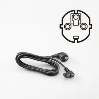
AC power cord for PWX750ML

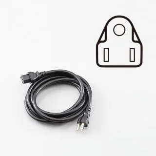
1500 W model AC power cord
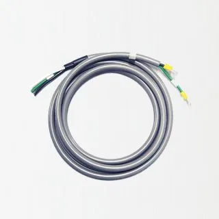
Parallel operation cable (For 2 units in parallel)

Parallel operation cable (For 3 units in parallel)

Parallel operation cable (For 4 units in parallel)

RS-232C conversion cable

GPIB Converter

Isolated analog interface

Variable internal resistance feature

Rack mount

Application Software

Downloads