Multifunctional Electronic Load (CC/CV/CR/CP)
PLZ-5W/5WZ Series
With high-speed response, this series supports dynamic load testing of power supplies and devices.<br/>Maximum slew rate: 540 A/μsec.


Product Overview
The New Flagship model is born! High-speed response, universal interface, large-scale system compatibility

Features
Color liquid crystal display (LCD)
Highly resolution color display allows for the convenient monitoring of values such as voltage, current, power, current capacity (Ah) and power capacity (Wh) all in the same place.
New numeric keypad for easy operation
Values can now be input directly from the front panel.
Industry’s highest slew rate of 540 A/μs
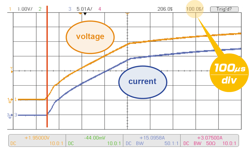
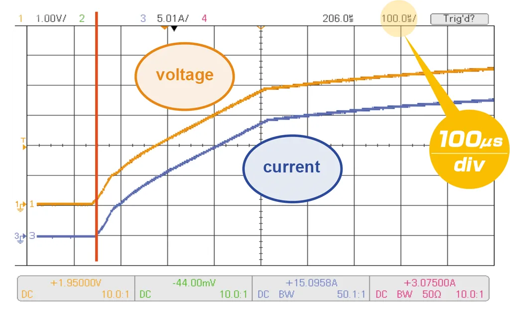
Achieves a rated current (*2160 A) rise time of 4 μs. Supports high-speed transient response testing, which is becoming increasingly significant for power supply evaluation.
*PLZ1205W + PLZ2405WB × 4 units
The slew rate increases proportionally to the number of units operating in parallel. Maximum slew rate of 60 A/μs can be set for the single PLZ1205W (rated current: 240 A).
Measurement conditions: equipment: PLZ1205W + PLZ2405WB × 4 units, capacitor load, load terminal voltage: 50 V, load current settings: 300 A/600 A/900 A/1200 A

Operation modes
The following five operation modes are available on the PLZ-5W. These can be selected when the load is in the off state.
| Constant current (CC) mode | A current value is specified and the current is kept constant even when the voltage changes. |
|---|---|
| Constant resistance (CR) mode | A conductance value is specified and the PLZ-5W sinks current proportional to the voltage variation. |
| Constant voltage (CV) mode | A voltage is specified and the PLZ-5W sinks current so that the voltage at the load input end of the PLZ-5W is constant. |
| Constant power (CP) mode | A voltage is specified and the PLZ-5W sinks current so that the power consumed inside the electronic load is constant. |
| Arbitrary I-V characteristics (ARB) mode | The desired load characteristics can be set by specifying multiple arbitrary voltage values and current values as I-V characteristics. |
Load On/Off
The following load on/off settings are available in addition to standard operations that can be carefully adjusted to fit the needs of any test environment.
- Start with “load on” when power is turned on
- Display elapsed “load on” time
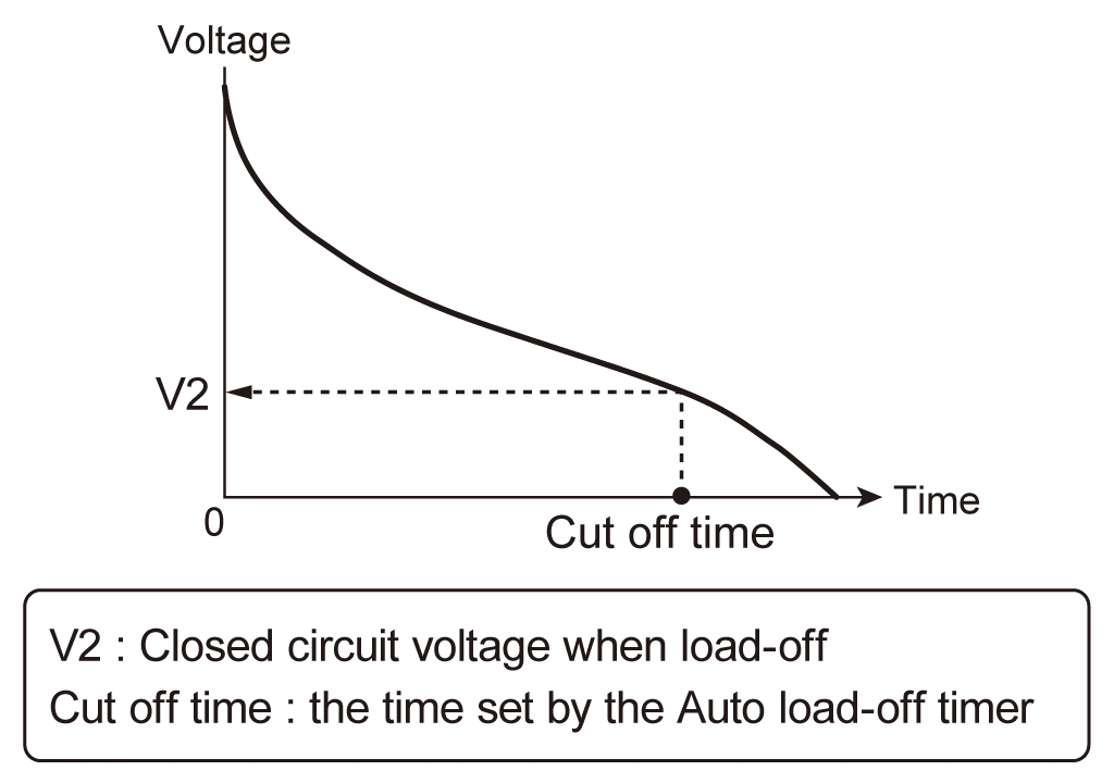
- Auto “load off” when time limit is reached
- Control “load on/off” with external controls such as relays
Adjustable slew rate
The speed of change can be set when the current is changed. The slew rate setting will function in the following instances.
- When the setting is changed to vary the current value (including the switching function).
- When the current value is changed using external control in constant current (CC) mode.
- When the current value is changed while the load is on.
Shift in the current waveform with the change in the slew rate
The slew rate is set according to the current range as an amount of current change per unit of time. Moreover, a common value is set for the rise and fall speeds. In CC mode and ARB mode, the slew rate can be set regardless of whether the load is on or off.

Arbitrary I-V characteristics: Installed “ARB mode”
In ARB mode arbitrary I-V characteristics can be set by entering multiple I-V points (voltage and current value set points). 3 to 100 points can be registered and the spaces between all points are automatically linearly interpolated. This mode can be used for the simulation of LED drivers and other DUT’s with non-linear characteristics.
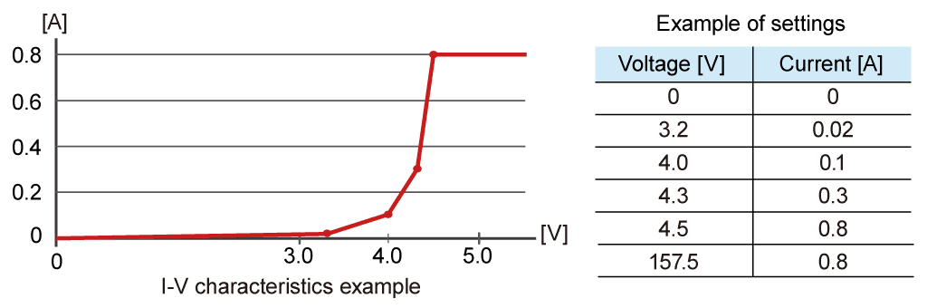
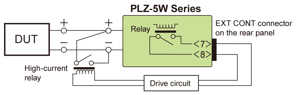
Short function
When the short function is activated, the maximum current value will be set if in CC mode, and the minimum voltage value will be set if in CR mode. The relay contact (30 Vdc/1 A) of the EXT CONT connector closes, and the load imput terminals can then be shorted by driving an external high-current relay.
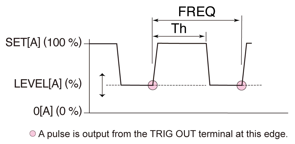
Setting parameters
- Operation mode: CC and CR
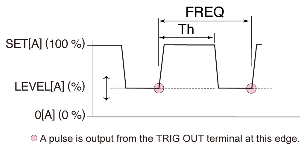
- Frequency setting range: 1 Hz to 100 kHz
- Frequency resolutionOpen in a new window
1 Hz to 10 Hz 0.1Hz 11 Hz to 100 Hz 1Hz 110Hz to 1kHz 10Hz 1.1kHz to 10kHz 0.1kHz 10 kHz to 100 kHz 20kHz, 50kHz, 100kHz - Frequency setting accuracy: ±(0.5 % of set)
- Duty cycle setting range, stepOpen in a new window
1 Hz to 10 Hz 5.0% to 95.0%, in steps of 0.1% 11 Hz to 100 Hz 110 Hz to 1000 Hz 1.1 kHz to 10.0 kHz 5.0% to 95.0%, in steps of 1% 10 kHz to 100 kHz 10% to 90%, in steps of 10% *The minimum time interval for setting the duty factor is 5 μs.
Soft start function
“Soft start” is a function that controls the rise time of the load current. “Soft start” functions only when all the following conditions are met:
- The rise time of the soft start has been set.
- “Load on” state is in constant current (CC) mode.
- Soft start input settings start from zero input and end equal to or above the minimum operating conditions.
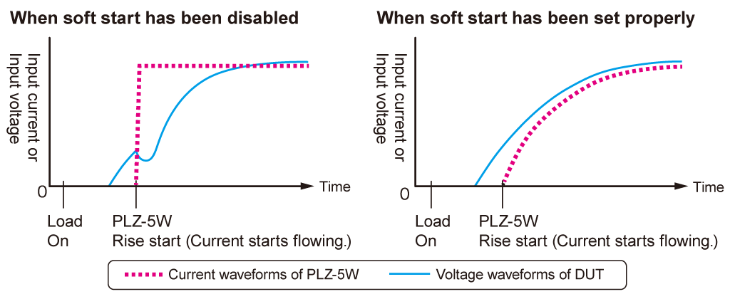
This function can be used if the output of the DUT becomes unstable when the load current rises sharply, or when the operator wishes to delay the current change on startup to prevent the DUT’s overcurrent protection circuit from being activated. Can be set to OFF / 100 μs / 200 μs / 500 μs / 1 ms / 2 ms / 5 ms / 10 ms / 20 ms. This sets the soft start time.
High precision and high resolution
The built-in three-range configuration provides wide dynamic range and high precision.
PLZ205W operating range and setting resolution
| Operating range | Resolution | ||
|---|---|---|---|
| Constant current mode | Range H Range M Range L | 0 A to 40 A 0 A to 4 A 0 A to 0.4 A | 1 mA 0.1 mA 0.01 mA |
| Constant resistance mode*1 | Range H Range M Range L | 40 S to 0.002 S 4 S to 0.0002 S 400 mS to 0.02 mS | 1 mS 0.1 mS 0.01 mS |
| Constant voltage mode | Range H Range L | 0.25 V to 150 V 0.25 V to 15 V | 5 mV 0.5 mV |
| Constant power mode | Range H Range M Range L | 20 W to 200 W 2 W to 20 W 0.2 W to 2 W | 0.005 W 0.0005 W 0.00005 W |
*1 Conductance [S] = Input current [A] / Input voltage [V] = 1 / Resistance [Ω]
Remote sensing function
With remote sensing, the voltage measurement point can be changed from the load input terminal to the DUT sensing point. By connecting the sensing leads to the DUT, the effects of voltage drops caused by resistance in the load cables can be reduced and the load current stabilized. To activate remote sensing, connect the sensing cables to the sensing terminals of the PLZ-5W at the DUT end, and enable the remote sensing function.
- Possible remote sensing compensation voltage : approx. 7 V
Sequence function
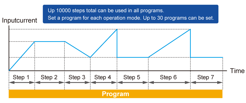
The operator can execute a long sequence of predetermined values with the sequence function. A sequence consists of programs and steps. A program is a collection of steps, which are executed in order, one by one, starting from step 1. The program is considered complete after the last step in the program is executed.
TALink
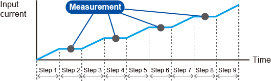
The operator can use the TALink (Transient Acquire Link) trigger to synchronize the PLZ-5W with steps of a sequence and enable data logging. Logged data can then be acessed via digital communication with the PLZ-5W.
| Setting item | Description |
|---|---|
| Load value | Current, conductance, voltage, power. The values that can be set depend on the current operation mode. |
| Step execution time | 0.000025s to 3600000s |
| Transition method of the current value | Step or Ramp |
| Number of loops of program | 1 to 100000 repetitions, or infinite repetitions. |
| Sequence editing / execution / stop method | Front panel operation or remote operation via RS232C / LAN / USB. |
| Others | Load on/off control, Slew Rate, CV mode addition, Trigger signal setting, trigger signal output, Specifies the value at which a protection function (OCP, OPP, UVP) is activated. |
Synchronized operation function
The following synchronization features are available when simply connecting the PLZ-5W with other equipment using a communication cable.
- Synchronizing load on/off among multiple pieces of equipment.
- Synchronizing measurements (remote control)
- Synchronizing the start time and resume time for sequences across multiple units
Different PLZ-5W models can be connected in a mixed configuration (e.g., PLZ205W and PLZ1205W). Synchronized operation is also possible during parallel operation.
Setup Memory
The setup memory can store up to 20 sets of the settings listed below.
- Operating mode (CC/CR/CV/CP, with or without +CV)
- Current/resistance/voltage/power value at storage
- Range setting
- Slew rate
- Switching interval (frequency/time of one cycle and duty cycle/operating time on the high side.)
- Protection setting
- ABC preset memory data
Communication Interface
LAN (LXI) / USB / RS232C as standard interface
*GPIB Option

ABC Preset Memories
Three setting values can be stored in preset memory slots A, B, and C. The stored values can be recalled freely at any time even when the load is on. In CC+CV and CR+CV modes, constant current and constant voltage values, as well as constant resistance and constant voltage values can be recalled and saved, respectively.
Diverse protections, other functions
Overcurrent protection (OCP), Overpower protection (OPP), Overvoltage detection(OVP), Undervoltage protection (UVP), Overheat detection(OTP), Reverse-connection detection(REV), Alarm input detection, Configuration setting, USB Keyboard Compliant
Booster (PLZ2405WB)
Achieving 2400 W in a “2U” chassis
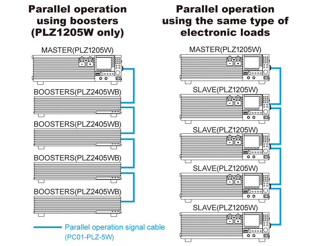
Connecting up to 4 booster (PLZ2405WB) units with the master (PLZ1205W) increases the maximum system capability to 10.8 kW 2160 A. The optional parallel cable (PC01-PLZ-5W) is required to connect between the master and slave/booster units.
Number of parallel connected units and capacities (maximum currents and maximum voltages)
| Slave unit | 1 unit | 2 units | 3 units | 4 units |
|---|---|---|---|---|
| PLZ2405WB | 720A / 3600W | 1200A / 6000W | 1680A / 8400W | 2160A / 10800W |
Parallel operation
Multiple units of the same type can be connected in parallel.
Additionally, during parallel operation without a booster, up to five units of the same model, including the master unit, can be connected in parallel (up to 6 kW/1200 A). The connection operates as single-control master-slave operation, allowing the entire system to be controlled and displayed from the master unit’s panel. Note that an optional parallel operation cable (PC01-PLZ-5W) is required for the connection, with the quantity depending on the number of units connected.
*The PLZ2405WB (Booster) comes with 1 pc. of parallel operation cable (PC01-PLZ-5W).
Number of parallel connected units and capacities (maximum currents and maximum voltages)
| Slave unit | 1 unit | 2 units | 3 units | 4 units |
|---|---|---|---|---|
| PLZ205W | 80 A / 400 W | 120 A / 600 W | 160 A / 800 W | 200 A / 1000 W |
| PLZ405W | 160 A / 800 W | 240 A / 1200 W | 320 A / 1600 W | 400 A / 2000 W |
| PLZ1205W | 480 A / 2400 W | 720 A / 3600 W | 960 A / 4800 W | 1200 A / 6000 W |
*Additional parallel operation calibration can achieve the same setting and measurement accuracy of a single unit.
Connection diagram
Connection diagram
Applications
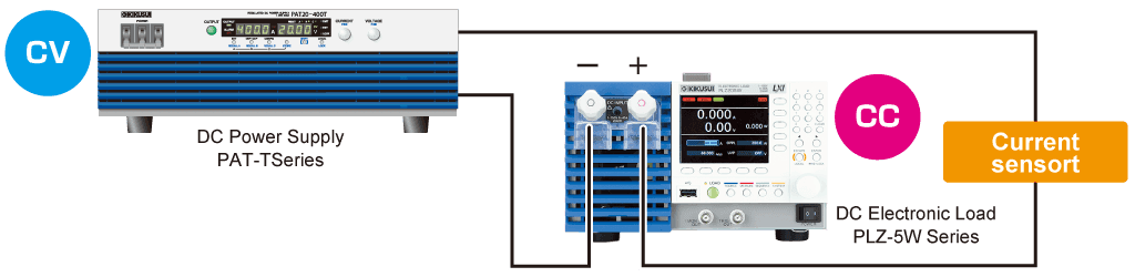
Current sensor evaluation
By configuring a high-precision constant-current power supply in combination with a DC power supply, it can also be used for applications such as evaluating current sensors. In addition, it is equipped with three range settings, allowing you to select the Current-setting Resolution that matches the Current value you want to set.
LED load simulation
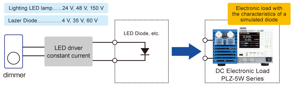
Arbitrary I-V characteristics (ARB) mode
In ARB mode arbitrary I-V characteristics can be set by entering multiple I-V points (voltage and current value set points). 3 to 100 points can be registered and the spaces between all points are automatically linearly interpolated. This mode can be used for the simulation of LED drivers and other DUT’s with non-linear characteristics.
Impedance measurement of the power supply
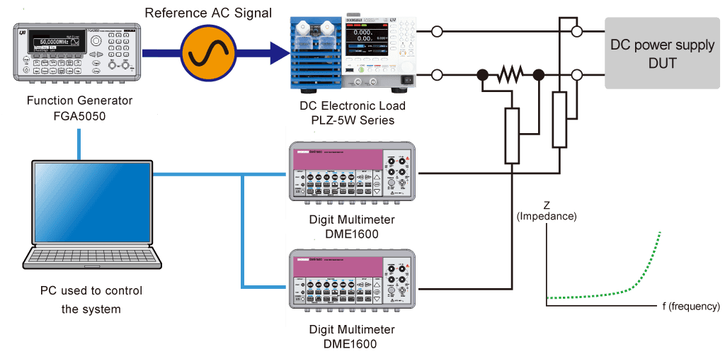
When using the PLZ-5W
Measure power supply impedance by configuring a system using the PLZ-5W, a function generator, and a digital multimeter.
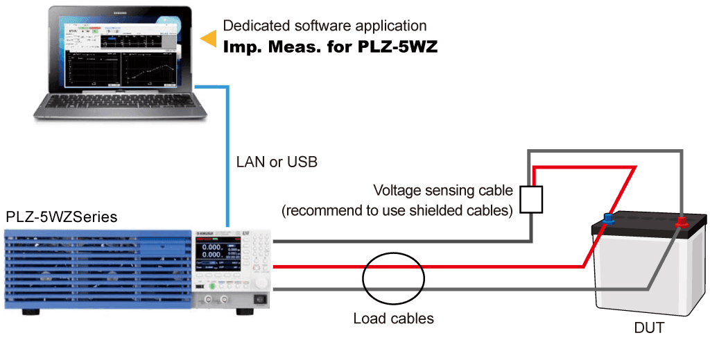
When using the PLZ-5WZ
A function generator is not necessary.

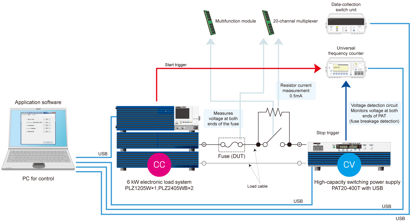
Fuse rupture test
In fuse blow tests, high‑speed current control is required when a DC power supply operates in constant current mode. Although a DC power supply alone has difficulty achieving such high‑speed control, combining it with the new electronic load PLZ‑5W enables high‑speed current control.
For fuse blow testing, the JASO D612 standard is required. The system can perform each test required by the standard (voltage drop test / transient Current interruption test / blow time test / step energization test / breaking capacity test).
Battery evaluation test
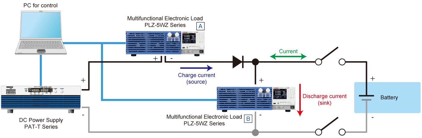
Although high-speed operation cannot be achieved using only the PAT-T high-capacity switching power supply, the fast-response unipolar power supply system can be suplemented by connecting with the PLZ-5W series electronic load in series and parallel. This makes it possible to flow current while synchronizing the charge and discharge current patterns for a battery at high speeds. Furthermore, the additional features of the PLZ-5WZ allow for seamless measurement of battery imedance during evaluation.
Specifications
Line-up
| Specifications | PLZ205W | PLZ405W | PLZ1205W | ||
|---|---|---|---|---|---|
| Rating | Operating voltage (V) | 0.25 to 150 | |||
| Current (A) | 40 | 80 | 240 | ||
| Power (W) | 200 | 400 | 1200 | ||
| Constant current mode (CC) | Setting range | H range (A) | 0 to 42 | 0 to 84 | 0 to 252 |
| M range (A) | 0 to 4.2 | 0 to 8.4 | 0 to 25.2 | ||
| L range (A) | 0 to 0.42 | 0 to 0.84 | 0 to 2.52 | ||
| Ripple | mArms | 4 | 8 | 24 | |
| Constant voltage mode (CV) | Setting range | H range (V) | 0 to 157.5 | ||
| L range (V) | 0 to 15.75 | ||||
| Resolution | H range (mV) | 5 | |||
| L range (mV) | 0.5 | ||||
| Constant resistance mode (CR) | Setting range | H range (S) | 42 to 0 | 84 to 0 | 252 to 0 |
| M range (S) | 4.2 to 0 | 8.4 to 0 | 25.2 to 0 | ||
| L range (mS) | 420 to 0 | 840 to 0 | 2520 to 0 | ||
| Constant power mode (CP) | Setting range | H range (W) | 0 to 210 | 0 to 420 | 0 to 1260 |
| M range (W) | 0 to 21 | 0 to 42 | 0 to 126 | ||
| L range (W) | 0 to 2.1 | 0 to 4.2 | 0 to 12.6 | ||
| Weight | kg/Ib | 7 | 7.5 | 14 | |
| Power | Approx. VA | 50 | 50 | 85 | |
Common specifications
Switching operation
Operation mode: CC and CR, Frequency range: 1.0 Hz to 100.0 kHz, Duty cycle setting range: 1% to 99%
Input voltage
100 Vac to 240 Vac (90 Vac to 250 Vac) single phase
Ratings
| Model | PLZ205W | PLZ405W | PLZ1205W |
|---|---|---|---|
| Operating voltage | 0.25 V to 150 V *1 | ||
| Current *2 | 40 A | 80 A | 240 A *3 |
| Power | 200W | 400W | 1200W |
| The minimum operating voltage | approximately 0.05 V. (At the load input terminals on the rear panel.) | ||
| Input resistance when the load is off | Approx. 660 kΩ *4 | ||
| Load input terminal’s isolation voltage | ±500 V | ||
*1 In switching mode, for every slew rate setting of 1 A/μs, the minimum operating voltage (including the voltage drop due to the wiring inductance component) increases by approx. 150 mV for the PLZ205W, approx. 125 mV for the PLZ405W, and approx. 75 mV for the PLZ1205W. *2 If the input voltage is 1 V or less, the current is reduced by 10% per 0.1 V. *3 80 A for the load input terminals on the front panel. The specifications of the PLZ-5W are for the load input terminals on the rear panel and the load input terminals on the front panel may not meet the specifications. *4 In the case of parallel operation using the same models, approx. 660/number of units kΩ.
Constant current (CC) mode
| Model | PLZ205W | PLZ405W | PLZ1205W | ||
|---|---|---|---|---|---|
| Operating range | Range H | 0 A to 40 A | 0 A to 80 A | 0 A to 240 A | |
| Range M | 0 A to 4 A | 0 A to 8 A | 0 A to 24 A | ||
| Range L | 0 A to 0.4 A | 0 A to 0.8 A | 0 A to 2.4 A | ||
| Setting range | Range H | 0 A to 42 A | 0 A to 84 A | 0 A to 252 A | |
| Range M | 0 A to 4.2 A | 0 A to 8.4 A | 0 A to 25.2 A | ||
| Range L | 0 A to 0.42 A | 0 A to 0.84 A | 0 A to 2.52 A | ||
| Resolution | Range H | 1 mA | 2 mA | 5 mA | |
| Range M | 0.1 mA | 0.2 mA | 0.5 mA | ||
| Range L | 0.01 mA | 0.02 mA | 0.05 mA | ||
| Setting accuracy | Range H | ±(0.2% of set + 0.1% of range) | |||
| Range M | ±(0.2% of set + 0.3% of range) | ||||
| Range L | ±(0.2% of set + 1% of range) | ||||
| Parallel operation | Range H | ±(0.4% of set + 0.8% of range) | |||
| Range M | ±(0.4% of set + 0.8% of range) | ||||
| Range L | ±(0.4% of set + 5% of range) | ||||
| Input line regulation *1 | 4 mA | 8 mA | 24 mA | ||
| Ripple | rms *2 | 4 mA | 8 mA | 24 mA | |
| p-p *3 | 40 mA | 80 mA | 200 mA | ||
*1 When the input voltage is changed from 1 V to 150 V at a current of rated power / 150 V. *2 Measurement frequency bandwidth: 10 Hz to 1 MHz *3 Measurement frequency bandwidth: 10 Hz to 20 MHz
Constant resistance (CR) mode
| Model | PLZ205W | PLZ405W | PLZ1205W | ||
|---|---|---|---|---|---|
| Operating range *1 | Range H | 40 S to 0.002 S (0.025 Ω to 500 Ω) | 80 S to 0.004 S (0.0125 Ω to 250 Ω) | 240 S to 0.012 S (0.0042 Ω to 83.333 Ω) | |
| Range M | 4 S to 0.0002 S (0.25 Ω to 5000 Ω) | 8 S to 0.0004 S (0.125 Ω to 2500 Ω) | 24 S to 0.0012 S (0.042 Ω to 833.33 Ω) | ||
| Range L | 400 mS to 0.02 mS (2.5 Ω to 50000 Ω) | 800 mS to 0.04 mS (1.25 Ω to 25000 Ω) | 2400 mS to 0.12 mS (0.42 Ω to 8333.3 Ω) | ||
| Setting range | Range H | 42 S to 0 S (0.0238 Ω to Open) | 84 S to 0 S (0.0119 Ω to Open) | 252 S to 0 S (0.00397 Ω to Open) | |
| Range M | 4.2 S to 0 S (0.238 Ω to Open) | 8.4 S to 0 S (0.119 Ω to Open) | 25.2 S to 0 S (0.0397 Ω to Open) | ||
| Range L | 420 mS to 0 S (2.38 Ω to Open) | 840 mS to 0 S (1.19 Ω to Open) | 2520 mS to 0 S (0.397 Ω to Open) | ||
| Resolution | Range H | 1 mS | 2 mS | 5 mS | |
| Range M | 0.1 mS | 0.2 mS | 0.5 mS | ||
| Range L | 0.01 mS | 0.02 mS | 0.05 mS | ||
| Setting accuracy *2 | Range H | ±(0.5% of set + 0.5% of range) | |||
| Range M | ±(0.5% of set + 0.5% of range) | ||||
| Range L | ±(0.5% of set + 1.5% of range) | ||||
| Parallel operation | Range H | ±(0.5% of set + 1.5% of range) | |||
| Range M | ±(0.5% of set + 1.5% of range) | ||||
| Range L | ±(0.5% of set + 5% of range) | ||||
*1 Conductance [S] = input current [A]/input voltage [V] = 1 / resistance [Ω] *2 Converted value at the input current. At the sensing terminals during remote sensing.
Constant voltage (CV) mode
| Model | PLZ205W | PLZ405W | PLZ1205W | |
|---|---|---|---|---|
| Operating range | Range H | 0.25 V to 150 V | ||
| Range L | 0.25 V to 15 V | |||
| Setting range | Range H | 0 V to 157.5 V | ||
| Range L | 0 V to 15.75 V | |||
| Resolution | Range H | 5 mV | ||
| Range L | 0.5 mV | |||
| Setting accuracy *1 | ±(0.1% of set + 0.1% of range) | |||
| Parallel operation | ±(0.2% of set + 0.2% of range) | |||
| Input voltage variation*2 | 12 mV | |||
*1 With the input voltage within the operating range, and at the sensing terminals during remote sensing. *2 For a current change in the range of 10% to 100% of the rating at an input voltage of 5 V (during remote sensing).
Constant power (CP) mode
| Model | PLZ205W | PLZ405W | PLZ1205W | ||
|---|---|---|---|---|---|
| Operating range | Range H | 20 W to 200 W | 40 W to 400 W | 120 W to 1200 W | |
| Range M | 2 W to 20 W | 4 W to 40 W | 12 W to 120 W | ||
| Range L | 0.2 W to 2 W | 0.4 W to 4 W | 1.2 W to 12 W | ||
| Setting range | Range H | 0 W to 210 W | 0 W to 420 W | 0 W to 1260 W | |
| Range M | 0 W to 21 W | 0 W to 42 W | 0 W to 126 W | ||
| Range L | 0 W to 2.1 W | 0 W to 4.2 W | 0 W to 12.6 W | ||
| Resolution | Range H | 0.005 W | 0.01 W | 0.05 W | |
| Range M | 0.0005 W | 0.001 W | 0.005 W | ||
| Range L | 0.00005 W | 0.0001 W | 0.0005 W | ||
| Setting accuracy | Range H | ±(0.5% of range + 0.04A×Vin *1) | ±(0.5% of range + 0.08A×Vin *1) | ±(0.5% of range + 0.24A×Vin *1) | |
| Range M | ±(0.5% of range + 0.008A×Vin *1) | ±(0.5% of range + 0.016A×Vin *1) | ±(0.5% of range + 0.048A×Vin *1) | ||
| Range L | ±(1% of range + 0.004A×Vin *1) | ±(1% of range + 0.008A×Vin *1) | ±(1% of range + 0.024A×Vin *1) | ||
| Parallel operation | Range H | ±(2% of range + 0.4% current range ×Vin *1) | |||
| Range M | ±(2% of range + 0.4% current range ×Vin *1) | ||||
| Range L | ±(2% of range + 2.5% current range ×Vin *1) | ||||
*1 Vin: Rear panel load input terminal voltage or sensing terminal voltage.
Arbitrary I-V characteristics (ARB) mode
| Model | PLZ205W | PLZ405W | PLZ1205W |
|---|---|---|---|
| Operating range | Three to 100 points of current values can be set for the input voltage. The space between two points is linearly interpolated. | ||
| Response speed | Response for input voltage minimum 50 μs. | ||
Voltmeter
| Model | PLZ205W | PLZ405W | PLZ1205W | |
|---|---|---|---|---|
| Display | Range H | 0.00 V to 150.00 V | ||
| Range L | 0.000 V to 15.000 V | |||
| Accuracy | ±(0.1% of reading + 0.1% of range) | |||
| Parallel operation (TYP) | ±(0.1% of reading + 0.1% of range) | |||
Ammeter
| Model | PLZ205W | PLZ405W | PLZ1205W | ||
|---|---|---|---|---|---|
| Display | Range H | 0.000 A to 40.000 A | 0.000 A to 80.000 A | 0.00 A to 240.00 A | |
| Range M | 0.0000 A to 4.0000 A | 0.0000 A to 8.0000 A | 0.000 A to 24.000 A | ||
| Range L | 0.00 mA to 400.00 mA | 0.00 mA to 800.00 mA | 0.0000 A to 2.4000 A | ||
| Accuracy | H, M range | ±(0.2% of reading + 0.3% of range) | |||
| Range L | ±(0.2% of reading + 1% of range) | ||||
| Parallel operation (TYP) | H, M range | ±(0.4% of reading + 0.8% of range) | |||
| Range L | ±(0.4% of reading + 5% of range) | ||||
Power display
| Model | PLZ205W | PLZ405W | PLZ1205W |
|---|---|---|---|
| Display | Displays the product of the voltmeter reading and ammeter reading. | ||
Switching function
| Model | PLZ205W | PLZ405W | PLZ1205W | |
|---|---|---|---|---|
| Operation mode | CC and CR | |||
| Frequency setting range | 1.0 Hz to 100.0 kHz | |||
| Frequency setting resolution | 1 Hz to 10 Hz | 0.1Hz | ||
| 11 Hz to 100 Hz | 1Hz | |||
| 110 Hz to 1000 Hz | 10Hz | |||
| 1.1 kHz to 10.0 kHz | 0.1kHz | |||
| 10 kHz to 100 kHz | 20 kHz, 50 kHz, 100 kHz | |||
| Frequency setting accuracy | ±(0.5% of set) | |||
| Duty cycle setting range, step *1 | 1 Hz to 10 Hz | 5.0% to 95.0%, 0.1% steps | ||
| 11 Hz to 100 Hz | ||||
| 110 Hz to 1000 Hz | ||||
| 1.1 kHz to 10.0 kHz | 5% to 95%, 1% steps | |||
| 10 kHz to 100 kHz | 10% to 90%, 10% steps | |||
*1 The minimum time span is 5 us. The minimum duty cycle is limited by the minimum time span.
Slew rate
| Model | PLZ205W | PLZ405W | PLZ1205W | |
|---|---|---|---|---|
| Operation mode | CC | |||
| Setting range | Range H | 0.01 A/ μs to 10 A/ μs | 0.02 A/ μs to 20 A/ μs | 0.06 A/ μs to 60 A/ μs |
| Range M | 0.001 A/ μs to 1 A/ μs | 0.002 A/ μs to 2 A/ μs | 0.006 A/ μs to 6 A/ μs | |
| Range L | 0.1 mA/ μs to 100 mA/ μs | 0.2 mA/ μs to 200 mA/ μs | 0.6 mA/ μs to 600 mA/ μs | |
| Resolution | Range H | 0.01A/μs | 0.02A/μs | 0.06A/μs |
| Range M | 0.001A/μs | 0.002A/μs | 0.006A/μs | |
| Range L | 0.1mA/μs | 0.2mA/μs | 0.6mA/μs | |
| Setting accuracy *1 | H, M range | ±(10% of set + 1.25μs) | ||
| Range L | ±(12% of set + 5μs) | |||
*1 Time to change from 10% to 90% when the current is changed from 0% to 100% of the rated current
Soft start
| Model | PLZ205W | PLZ405W | PLZ1205W |
|---|---|---|---|
| Operation mode | CC | ||
| Time setting range | 100 μs, 200 μs, 500 μs, 1 ms, 2 ms, 5 ms, 10 ms, 20 ms, or off | ||
| Time accuracy | ±(30% of set +10μs) | ||
Possible remote sensing compensation voltage
| Model | PLZ205W | PLZ405W | PLZ1205W |
|---|---|---|---|
| compensation voltage | Approx. 7 V (total potential difference between the input terminals and sensing terminals). | ||
Protective function
| Model | PLZ205W | PLZ405W | PLZ1205W | |
|---|---|---|---|---|
| Overcurrent protection (OCP) | Setting range | 0.0 A to 44.0 A | 0.0 A to 88.0 A | 0.0 A to 264.0 A |
| Resolution | 10mA | 10mA | 10mA | |
| Protective operation | Either load off or limitation can be selected. | |||
| Overpower protection (OPP) | Setting range | 0 W to 220 W | 0 W to 440 W | 0 W to 1320 W |
| Resolution | 0.1W | 0.1W | 0.1W | |
| Protective operation | Either load off or limitation can be selected. | |||
| Undervoltage protection (UVP) | Setting range | 0.00 V to 150.00 V, or off | ||
| Resolution | 0.01V | |||
| Protective operation | Load off | |||
| Watchdog protection(WDP) | Setting range | 1 s to 3600 s or off | ||
| Protective operation | Load off | |||
Sequence function
| Model | PLZ205W | PLZ405W | PLZ1205W |
|---|---|---|---|
| Operation mode | CC, CR, CV, CP | ||
| Maximum number of programs | 30 | ||
| Maximum number of steps | 10000 | ||
| Step execution time | 25 μs to 1000 h | ||
| Time resolution | 1μs | ||
Other functions
| Model | PLZ205W | PLZ405W | PLZ1205W | |
|---|---|---|---|---|
| Elapsed time display | Displays the time from load on to load off. | |||
| Range | 1s to 999h 59min 59s. | |||
| Integrated current display | Displays the integrated current from load on to load off. | |||
| Integrated power display | Displays the integrated power from load on to load off. | |||
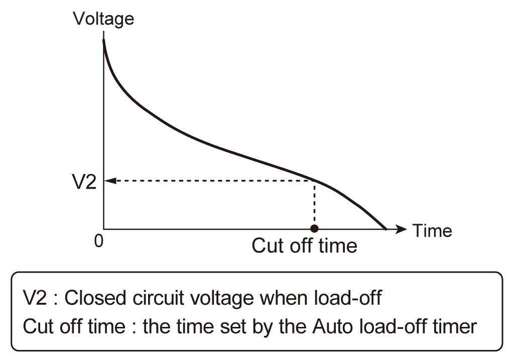
| Auto load off timer | Automatically turns off the load after the specified time elapses. | |||
| Setting range | 1s to 3599999s, or off. | |||
EXT CONT connector
| Model | PLZ205W | PLZ405W | PLZ1205W | |
|---|---|---|---|---|
| Load on/off control input | Logic level switchable. Pulled up to 5 V by a 10 kΩ resistor. The thresholds are HIGH: 3.5 V to 5 V, LOW: 0 V to 1.5 V. | |||
| Range control input | The range can be switched between L, M, and H using a 2 bit signal. Pulled up to 5 V by a 10 kΩ resistor. The thresholds are HIGH: 3.5 V to 5 V, LOW: 0 V to 1.5 V. | |||
| Alarm input | An alarm is activated with a voltage between 0 V and 1.5 V. Pulled up to 5 V by a 10 kΩ resistor. The thresholds are HIGH: 3.5 V to 5 V, LOW: 0 V to 1.5 V. | |||
| Alarm clearing input | After an alarm occurs, eliminate the root cause of the alarm, and change the input to pin 5 of the EXT CONT connector from a low level signal to a high level signal. The alarm will be cleared on the rising edge of this signal. Pulled up to 5 V by a 10 kΩ resistor. The thresholds are HIGH: 3.5 V to 5.0 V, LOW: 0 V to 1.5 V. | |||
| Trigger input | Paused sequence operation resumes when a voltage between 0 V and 0.8 V is received. Pulled up to 5 V by a 10 kΩ resistor. The thresholds are HIGH: 2 V to 5 V, LOW: 0 V to 0.8 V. | |||
| External voltage control input (CC, CR, CP mode) | Controls the load settings of CC, CR, CP mode through external voltage input. The input impedance is approx. 10 kΩ. CC: The setting can be controlled in the range of 0% to 100% of the rated current through external voltage input of 0 V to 10 V. CR: The setting can be controlled in the range of 0% to 100% of the conductance setting through external voltage input of 0 V to 10 V. CP: The setting can be controlled in the range of 0% to 100% of the rated power through external voltage input of 0 V to 10 V. | |||
| Setting accuracy | ± (1% of range) (TYP value of H range in CC mode) | |||
| External voltage control input (CV mode) | The load setting of CV mode can be controlled through external voltage input. The rated voltage can be controlled in the range of 0% to 100% with 0 V to 10 V. The input impedance is approx. 10 kΩ. | |||
| Setting accuracy | ± (1% of range) (TYP value) | |||
| External voltage control input (superimposing in CC mode) | Controls the load setting of CC mode by adding current through external voltage input. Adds current in the range of -100% to 100% of the rated current for -10 V to 10 V. The input impedance is approx. 10 kΩ. | |||
| Setting accuracy | ± (1% of range) (TYP value of H range) | |||
| Load-on status output | On when load is on. Open-collector output from a photocoupler. *1 | |||
| Range status output | Outputs current range state L, M, and H using 2 bits. Open-collector output from a photocoupler. *1 | |||
| ALARM 1 output | Turns on when overvoltage detection, reverse-connection detection, overheat detection, alarm input detection, front-panel load input terminal overcurrent detection, or parallel operation anomaly detection is activated. Open-collector output from a photocoupler. *1 | |||
| ALARM 2 output | Turns on when OCP, OPP, UVP, or WDP is activated. | |||
| DIGITAL 0 / DIGITAL 1 output | Logic signal output during a step of a sequence. Output impedance: approx. 330 Ω, output voltage: approx. 3.3 VEMF | |||
| DIGITAL 2 output | Input/output switchable. Output: Logic signal output during a step of a sequence. The output impedance is 330 Ω.Input: Trigger input signal for the sequence and the measurement functions. The thresholds are HIGH: 2 V to 5 V, LOW: 0 V to 0.8 V. | |||
| Current monitor output | Outputs 0 V to 10 V for 0% to 100% of the rated current of each range. | |||
| Accuracy | ± (1% of range) (TYP value of H range) | |||
| Short signal output | Relay contact turns on when the short function is turned on (30 Vdc/1 A). | |||
*1 The maximum voltage that can be applied to the photocoupler is 30 V. The maximum current is 4 mA.
BNC connector
| Model | PLZ205W | PLZ405W | PLZ1205W | |
|---|---|---|---|---|
| Trigger output | Transmits 10 μs pulses when trigger output is ON during sequence operation and during step execution. Transmits 1 μs pulses during switching operation. | |||
| Current monitor output | Outputs 0 V to 2 V for 0% to 100% of the rated current of each range. | |||
| Accuracy | ± (1% of range) (TYP value of H range) | |||
| Isolation voltage | ±30V | |||
Communication function
| Model | PLZ205W | PLZ405W | PLZ1205W |
|---|---|---|---|
| LAN | IEEE 802,3 100Base-TX / 10Base-T Ethernet IPv4, RJ-45 connector | ||
| RS232C | D-SUB 9-pin connector Baud rate: 9600, 19200, 38400, 115200 bps Data length: 8 bits, Stop bits: 1 bit, Parity bit: None, Flow control: None, CTS-RTS | ||
| USB | Complies with the USB 2.0 specification. Data rate: 480 Mbps (High speed) Complies with the USBT MC-USB488 device class specifications. | ||
General specifications
| Model | PLZ205W | PLZ405W | PLZ1205W | |
|---|---|---|---|---|
| Input voltage range/ Input frequency range | 100 Vac to 240 Vac (90 Vac to 250 Vac) single phase, continuous / 47 Hz to 63 Hz | |||
| Power consumption | 50VAmax | 50VAmax | 85VAmax | |
| Inrush current | 45A Peak | |||
| Environmental conditions | Operating temperature range / Operating humidity range | 0 °C to 40 °C (32 °F to 104°F) / 20%rh to 85%rh (no condensation) | ||
| Storage temperature range / Storage humidity range | -20 °C to 70 °C (-4 °F to 158°F) / 90%rh or less (no condensation) | |||
| Installation location | Indoor use, altitude of up to 2000 m, overvoltage category II. | |||
| Insulation resistance | Between primary and input terminals | 500Vdc, 30 MΩ or more (70%rh or less) | ||
| Between primary and chassis | ||||
| Between input terminals and chassis | ||||
| Withstanding voltage | Between primary and input terminals | No abnormalities at 1500 Vac for 1 minute. | ||
| Between primary and chassis | No abnormalities at 1500 Vac for 1 minute. | |||
| Between input terminals and chassis | No abnormalities at 750 Vac for 1 minute. | |||
| Dimensions Unit: mm (inches) | 214.5 (8.45)W×124 (4.88)H×400 (15.75)Dmm(inches) | 429.5 (16.91)W×128 (5.04)H×400 (15.75)Dmm(inches) | ||
| Weight | Approx. 7 kg (15.4 lb.) | Approx. 7.5 kg (16.5 lb.) | Approx. 14 kg (30.9 lbs) | |
| Accessories | Power cord, Rear-panel load input terminal cover, Load input terminal screw set (2 sets), Screws for the rear-panel load input terminal cover (2 pcs.), Front-panel load input terminal cover, Front-panel load input knob set, External control connector kit, Setup Guide, CD-ROM, Quick Reference, Safety Information | |||
| Electromagnetic compatibility (EMC) *1*2 | Complies with the requirements of the following directive and standards. EMC Directive 2014/30/EU, EN 61326-1 (Class A*3), EN 55011 (Class A*3, Group 1*4), EN 61000-3-2, EN 61000-3-3 Applicable under the following conditions.The maximum length of all cabling and wiring connected to the PLZ-5W must be less than 3 m. | |||
| Safety *1 | Complies with the requirements of the following directive and standards. Low Voltage Directive 2014/35/EU *2 EN 61010-1 (Class I *5, Pollution Degree 2 *6) | |||
*1 Does not apply to specially ordered or modified PLZ-5Ws. *2 Only for models with have CE mark/UKCA mark on their body. *3 This is a Class A equipment. This product is intended for use in an industrial environment. This product may cause interference if used in residential areas. Such use must be avoided unless the user takes special measures to reduce electromag-netic emissions to prevent interference to the reception of radio and television broadcasts. *4 This is a Group 1 equipment. This product does not generate and/or use intentionally radio-frequency energy, in the form of electromagnetic radiation, inductive and/or capacitive coupling, for the treatment of material or inspection/analysis purpose. *5 This is a Class I equipment. Be sure to ground this product’s protective conductor terminal. The safety of this product is only guaranteed when the product is properly grounded. *6 Pollution is addition of foreign matter (solid, liquid or gaseous) that may produce a reduction of dielectric strength or surface resistivity. Pollution Degree 2 assumes that only non-conductive pollution will occur except for an occasional temporary con-ductivity caused by condensation.
Lineup


Options
GPIB Converter

Parallel Operation Signal Cable Kit


Sequence creation software “Wavy”

Rack Adapter/Bracket Option
PLZ205W、PLZ405W

PLZ1205W

*When using a blank panel for rack adapter, use KBP3-2.
Resources
Product Catalog
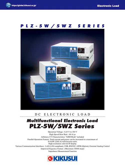
Multifunctional Electronic Load PLZ-5W/5WZSeries
https://global.kikusui.co.jp/download/cat_plz-5w-5wz/
Solutions

Power supply for DC motor evaluation
https://global.kikusui.co.jp/kikusui-solutions/dc-motor/
Evaluation of Power Supplies for Data Centers and IT Servers
https://global.kikusui.co.jp/kikusui-solutions/data-center/