


Function Generator
FGA5050
150,000円 (税込:165,000円)
- Wideband Oscillation Frequency
Sine wave: 1μHz to 50MHz, Square wave: 1μHz to 25MHz - Sine wave, square wave, ramp wave, triangle wave, pulse wave, noise wave, DC, arbitrary waveform output
- Application software for arbitrary waveform creation WAVEPATT included as standard
- Various modulation functions
AM, FM, PM, FSK, PWM, frequency sweep, burst, external modulation input - 16-bit / 50MHz pattern output
- 14-bit / 256K points, 125M samples/s arbitrary waveform
- 10MHz clock input/output
- Trigger input/output (TTL compatible)
- LAN / USB standard equipment
※Production has ended, available while stocks last.
Out of stock
Product Overview
LXI Compatibility Makes System Upgrades more Convenient
The FGA5050 is a function generator equipped with arbitrary waveform capabilities. In addition to a wide range of arbitrary waveform generation functions such as sine waves, square waves, ramp waves, and triangle waves, it offers a wide bandwidth of 50MHz and high resolution of 1μHz to achieve high-precision waveforms. It can be used in various markets, including automotive electrical equipment power fluctuation tests, ECU pseudo signal sources, secondary battery charge/discharge tests, pseudo battery charge/discharge tests, ripple superimposition tests, and as a trigger source for various test systems. Furthermore, it features both LAN and USB interfaces, catering to both manual and automated testing needs.
Usage Examples
Power Fluctuation Tests for Automotive Electrical Equipment
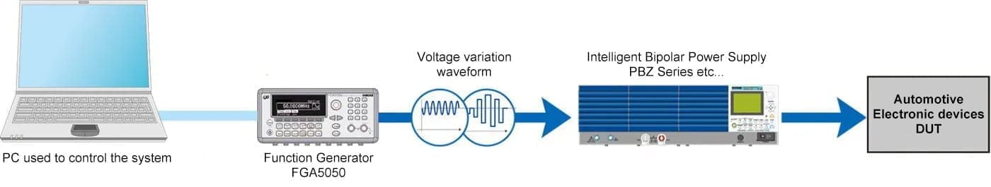
By combining the FGA5050 with a bipolar power supply, it can be used as a signal source for “power fluctuation tests for automotive electrical equipment” in compliance with ISO standards and various automotive manufacturer standards.
Measurement of Power Output Impedance
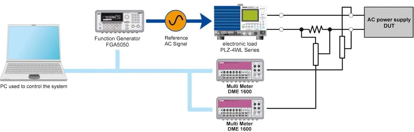
By combining the FGA5050 with an electronic load device and a function generator, it can be used as a reference AC signal source for “measurement of power output impedance.”
Specifications
General Specifications
| Input voltage range | Single-phase 100 Vac to 240 Vac, 50 Hz to 60 Hz , Single-phase 100 Vac to 120 Vac, 400 Hz |
|---|---|
| Power consumption | 80 VA max |
| Operating temperature range | 0 °C to 55 °C (80 %rh or less, no condensation) |
| Storage temperature range | -30 °C to 70 °C (80 %rh or less, no condensation) |
| Operating altitude | Up to 2000 m |
| Dimensions (mm)/ Weight | 253W × 107H × 381D mm (9.96W × 4.21H × 15.0D inch)/ Approx. 4 kg(8.8 lb) |
| Interface | LAN, USB, GPIB (factory option) |
| Accessories | “Power cord” 1 pc. (with three-pronged plug), “Pattern generator cable” 1pc., “USB cable” 1pc., “CD-R”*1 1pc., “Packing list,safety precautions” 1 English, 1 Japanese, “China RoHS disclosure report” 1pc. |
| Electromagnetic compatibility (EMC) *2*3 | Complies with the requirements of the following directive and standard. EMC Directive 2014/30/EU EN 61326-1(Class A*4) EN 55011(Class A, Group 1) EN 61000-3-2, EN 61000-3-3 |
| Safety*2 | Complies with the requirements of the following directive and standard. Low Voltage Directive 2014/35/EU EN 61010-1(Class I, Pollution degree 2) |
*1 including the “Operation Manual” and “Communication Interface Manual”.
Waveform Characteristics
| Waveforms | Standard waveforms | Sine, square, ramp, triangle, pulse, noise, and DC | ||
|---|---|---|---|---|
| Arbitrary waveforms | Exponential rising wave, exponential falling wave, reverse ramp wave, sinc wave, and cardiac wave (cardiac electrogram wave) | |||
| Sine | Frequency | 1 μHz to 50 MHz | ||
| Amplitude flatness *1 *2 (relative to 1 kHz) | Less than 100 kHz | 0.1 dB | ||
| Less than 5 MHz | 0.15 dB | |||
| Less than 20 MHz | 0.3 dB | |||
| Less than 50 MHz | 0.5 dB | |||
| Harmonic distortion *2 *3 | DC to 20 kHz | Less than 1 Vpp | -70 dBc | |
| 1 Vpp or more | -70 dBc | |||
| 20 kHz to 100 kHz | Less than 1 Vpp | -65 dBc | ||
| 1 Vpp or more | -60 dBc | |||
| 100 kHz to 1 MHz | Less than 1 Vpp | -50 dBc | ||
| 1 Vpp or more | -45 dBc | |||
| 1 MHz to 20 MHz | Less than 1 Vpp | -40 dBc | ||
| 1 Vpp or more | -35 dBc | |||
| 20 MHz to 50 MHz | Less than 1 Vpp | -35 dBc | ||
| 1 Vpp or more | -30 dBc | |||
| Total harmonic distortion | DC to 20 kHz | 0.5 Vpp or more | 0.06 % or less | |
| Spurious *2 *4 (non-harmonic) | DC to 1 MHz | -70 dBc | ||
| 1 MHz to 50 MHz | -70 dBc + 6 dB/octave | |||
| Phase noise (10 kHz offset) | 1 MHz or more | 0.1 Vpp or more | Typically -115 dBc/Hz | |
| Square waves | Frequency | 1 μHz to 25 MHz | ||
| Rising, falling time | Less than 10 ns | |||
| Overshoot | Less than 2 % | |||
| Variable duty cycle | Less than 10 MHz | 20 % to 80 % | ||
| Less than 25 MHz | 40 % to 60 % | |||
| Asymmetry | 50 % duty cycle | 1 % of period + 5 ns | ||
| Jitter (RMS) | 0.1 Vpp or more 1 MHz or more | 200 ps | ||
| Ramp and triangle waves | Frequency | 1 μHz to 200 kHz | ||
| Linearity | Less than 0.1 % of the peak output | |||
| Symmetry | 0.0 % to 100.0 % | |||
| Pulse wave | Frequency | 500 μHz to 10 MHz | ||
| Pulse width | 20 ns minimum | |||
| Resolution (period ≤ 10 s) | 10 ns | |||
| Variable edge time | Less than 10 ns to 100 ns | |||
| Overshoot | Less than 2 % | |||
| Jitter (RMS) | 0.1 Vpp or more 50 kHz or more | 200 ps | ||
| Noise waves | Bandwidth | Typically 20 MHz | ||
| Arbitrary waveforms | Frequency | 1 μHz to 10 MHz | ||
| Wavelength | 2 to 256 K points | |||
| Resolution | 14 bits (including the sign) | |||
| Sampling rate | 125 megasamples per second | |||
| Minimum rising or falling time | Typically 30 ns | |||
| Linearity | Less than 0.1 % of the peak output | |||
| Settling time | Up to 0.5 % of the final value | Less than 250 ns | ||
| Jitter (RMS) | 6 ns + 30 ppm | |||
| Non-volatile memory | 50 % duty cycle | 4 waveforms, 256 K points per waveform | ||
*1 Add 1/10th to the output amplitude and DC offset specifications per 1 oC for operations out-side the range of 18 oC to 28 oC. *2 When autoranging is enabled *3 DC offset set to 0 V *4 Spurious output at low amplitudes is typically -75 dBm.
Common specifications for waveform characteristics
| Frequency | Resolution | 1μHz |
|---|---|---|
| Amplitude | Range | 10 mVpp to 10 Vpp (50 Ω termination) , 20 mVpp to 20 Vpp (No termination) |
| Accuracy*1*2 | ±1 % of setting ± 1 mVpp (At 1 kHz) | |
| Units | Vpp, Vrms, and dBm | |
| Resolution | 4 digits | |
| DC offset | Range | ±5 V (50 Ω termination), ±10 V (No termination) |
| Accuracy*1*2 | ±2 % of offset setting ±0.5 % of amplitude setting ±2 mV | |
| Resolution | 4 digits | |
| Main Output | Impedance | Typically 50 Ω |
| Isolation | Up to 42 Vpk (From earth) | |
| Protection | Short-circuit protection, overload automatically stops output | |
| Internal frequency reference | Accuracy*2 | ±10 ppm (90 days), ±20 ppm (1 year) |
| External frequency reference input | Lock range | 10 MHz ± 500 Hz |
| Level | 100 mVpp to 5 Vpp | |
| Impedance | Typically 1 kΩ (AC coupled) | |
| Lock time | Less than 2 s | |
| Frequency reference output | Level | Typically 632 mVpp (0 dBm) |
| Impedance | Typically 50 Ω (AC coupled) | |
| Phase offset | Range | -360 ° to +360 ° |
| Resolution | 0.001° | |
| Accuracy | 8ns |
*1 When autoranging is enabled *2 Add 1 ppm/1 oC (average) for operations outside the range of 18 ℃ to 28 ℃.
Types of Modulation
| Types of modulation | Modulation | AM, FM, PM, FSK, PWM, sweep, and burst |
|---|---|---|
| AM | Carrier wave | Sine, square, ramp, or arbitrary |
| Modulation signal | Internal or external | |
| Internal modulation signal | Sine, square, ramp, triangle, noise, or arbitrary | |
| Internal modulation signal frequency range | 2 mHz to 20 kHz | |
| Modulation depth | 0.0 % to 120.0 % | |
| FM | Carrier wave | Sine, square, ramp, or arbitrary |
| Modulation signal | Internal or external | |
| Internal modulation signal | Sine, square, ramp, triangle, noise, or arbitrary | |
| Internal modulation signal frequency range | 2 mHz to 20 kHz | |
| Deviation | DC to 25 MHz | |
| PM | Carrier wave | Sine, square, ramp, or arbitrary |
| Modulation signal | Internal or external | |
| Internal modulation signal | Sine, square, ramp, triangle, noise, or arbitrary | |
| Internal modulation signal frequency range | 2 mHz to 20 kHz | |
| Deviation | 0.0 ° to 360 ° | |
| PWM | Carrier wave | Pulse wave |
| Modulation signal | Internal or external | |
| Internal modulation signal | Sine, square, ramp, triangle, noise, or arbitrary | |
| Internal modulation signal frequency range | 2 mHz to 20 kHz | |
| Deviation | 0 % to 100 % of the pulse width | |
| FSK | Carrier wave | Sine, square, ramp, or arbitrary |
| Modulation signal | Internal or external | |
| Internal modulation signal | Square wave signal with a 50 % duty cycle | |
| Internal modulation signal frequency range | 2 mHz to 100 kHz | |
| External Modulation Input*1 | Input voltage range | ±5 V full scale |
| Input resistance | Typically 8.7 kΩ | |
| Bandwidth | DC to 20 kHz | |
| Sweep | Waveforms | Sine, square, ramp, or arbitrary |
| Method | Linear and logarithmic | |
| Direction | Up, down | |
| Sweep time | 1 ms to 500 s | |
| Trigger | Internal, external, or manual | |
| Marker | The falling edge of the sync output signal | |
| Burst | Waveforms*2 | Sine, square, ramp, triangle, noise, or arbitrary |
| Method | Internal or external | |
| Starting and ending phases | -360 ° to +360 ° | |
| Internal period | 1 μs to 500 s | |
| Gate signal | External | |
| Trigger | Internal, external, or manual | |
| Trigger input | Input level | TTL compatible |
| Slope | Select rising or falling | |
| Pulse width | Greater than 100 ns | |
| Impedance | Greater than 10 kΩ (DC coupling) | |
| Latency | Less than 500 ns | |
| Trigger output | Output Level | TTL equivalent (load of 1 kΩ or more) |
| Pulse width | Greater than 400 ns | |
| Impedance | Typically 50 Ω | |
| Maximum speed | 1 MHz | |
| Fan-out | Up to 4 FGA5050s |
*1 FSK modulation uses the Trig In/Out, FSK/Burst connector (the maximum frequency is 1 MHz). *2 Sine and square waveforms above 10 MHz are can only be used with an infinite burst count.
Pattern Output
| Output | Maximum clock speed | 50 MHz |
|---|---|---|
| Output Level | TTL equivalent (load of 2 kΩ or more) | |
| Output Impedance | Typically 110 Ω | |
| Pattern Length | 2 to 256 K points |

