Probe calibration is an essential part of using an oscilloscope. In this article we revisit the basics of calibration
When the Waveform Does Not Mach the Calibration Chart
I mainly work with surge testers used in the testing of automotive device. Sometimes a customer will say, “We recently installed a Kikusui instrument. We purchased a X100 probe, which we were told we needed for waveform measurement. However, the displayed waveform differed from the waveform shown on the calibration chart. Why is this?”
When I dig further, it usually transpires that the oscilloscope and the circuit had been configured correctly,*1 but that the client had not calibrated the X100 probe.
Generally speaking, probes need to be calibrated (adjusted) to the oscilloscope they are to be used with. This step needs to be performed to ensure that the probe is working and capable of correct measurement.*2 This said, if the waveforms being measured are in the order of milliseconds or more (or even in the order of microseconds in some cases) or only the maximum and minimum voltages need to be measured, it is usually fine to use an uncalibrated probe. When using a passive probe to measure rise time and wavelengths in the order of nanoseconds or microseconds, however, it is imperative that the probe be correctly calibrated.
*1Some models of oscilloscope need to be floated with an isolation transformer.
*2Consult the probe manufacturer for their advice on calibration.
Problems are Usually Due to Incorrect Probe Calibration
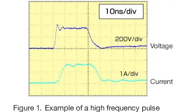
An oscilloscope with a high bandwidth and a high sampling rate is required to measure rise time and high-frequency pulses in the order of nanoseconds. If the device being tested has a coaxial structure with an output impedance of 50 ohms, it can be connected directly to an oscilloscope and pulse generator by using a coaxial attenuator or coaxial cable.*3This approach will enable waveforms to be measured with little signal loss or skew error. The specifications of the devices generally referred to as “surge generators” are determined in accordance with international, regional, and manufacturers standards: most do not have a 50 ohm coaxial output. It is therefore necessary to perform measurement using a differential probe or a passive probe. However, this can result in the waveform displayed differing from the waveform shown in the calibration chart for the device under test. Most enquiries of differing results involve waveforms that have a rise time in the nanosecond to microsecond range, which causes an error in the measurement due to improper calibration.*4
Enquiries regarding waveform measurement using differential probes include:
- Waveform not correctly displayed despite the use of an oscilloscope and probe recommended by Kikusui
- Error in measurement despite the probe having been calibrated by Kikusui
- Completely different measurement returned when the oscilloscope is swapped for a different oscilloscope having the same bandwidth
*3 The oscilloscope input needs to be terminated with a 50 ohm terminating impedance.
*4 Refers to enquiries received concerning Kikusui testing equipment.
The Short Answer
My responses to the enquiries above are as follows:
Q. Waveform not correctly displayed despite the use of an oscilloscope and probe recommended by Kikusui
A. The probe needs to be calibrated to the oscilloscope.
Q. Error in measurement despite the probe having been calibrated by Kikusui
A. A probe that has been calibrated on its own will give different results depending on the oscilloscope it is used with. (You should have been informed that measurements will contain errors unless the probe is calibrated to the oscilloscope.)
Q. Completely different measurement returned when the oscilloscope is swapped for a different oscilloscope having the same bandwidth
A. Changing the input capacitance will alter the reading, even at the same bandwidth and sampling rate (i.e. changing the input capacitance will return a different measurement, even when the same oscilloscope is used).
The use of oscilloscopes is a basic part of electronic measurement, and something in which most electrical engineers are trained in early in their careers. While for veteran engineers, oscilloscope use is a basic and common-sense part of using the tools of the trade, for those who are less experienced, or only use oscilloscopes occasionally, there is a surprising tendency to forget (or be confused about) how to tune or calibrate oscilloscope probes.
The short answer to these questions, then, is that in order to correctly measure waveforms, it is therefore important to perform calibration with the probe connected to the oscilloscope being used.
Deciding this concept would be more interesting if explained with some examples, I tried comparing the measurements I got on a range of oscilloscopes. The results are set forth over the page. I am lucky to work in an environment where high-voltage pulse generators and various models of oscilloscope are easy to come by. I wanted to see just how much variation there was between the various devices. While the results were more or less as expected, this type of experiment is unusual and not often performed. Hopefully you will find the results interesting.
First Calibrate the Probe
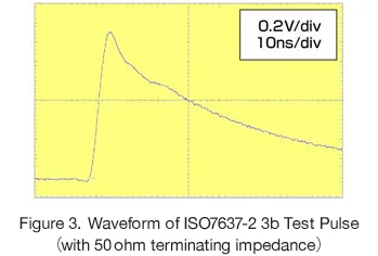
As mentioned above, it is generally necessary to calibrate any probe attached to an oscilloscope measuring data. The probe is calibrated using the square waves produced by the oscilloscope’s calibration (CAL) terminal.*5 However, the calibration terminal of this particular oscilloscope only produces pulses with an amplitude of V (a maximum of around 5V). The voltage of surge waveforms ranges from the tens to even hundreds of volts meaning that a passive probe with an attenuation rate of X100 or X1000 would be required. Connecting such a probe to the oscilloscope’s calibration terminals would yield a waveform with almost zero amplitude. Also, the calibration of a X100 or X1000 probe would require a high-voltage (square wave) pulse generator. Such devices are extremely expensive and difficult to come by, and therefore in my experiment I used a more realistic 3b test pulse generated by an ISO7637-2 testing device connected to a X100 differential (passive) probe.*6
*5 On some oscilloscopes, calibration terminals are labelled differently.
*6 The details of how correction is performed and matters to note when performing correction have been left out here.
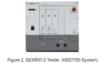
The 3b output on Kikusui’s ISO7637-2 testing devices (KES7700 systems) has a 50 ohm coaxial structure. This means that the device can to be connected directly to an oscilloscope with the use of an attenuator or similar, meaning that the output waveform can be measured with little loss or skew. When measuring with a passive probe, the use of an adapter to convert the probe terminal to a BNC connector lessens the effects of extending the earth terminal, a practice that significantly impacts probe measurement. With an output of 300 V (or 150 V when using a 50 ohm terminator), this setup provides ample voltage, making it suitable for measuring the differences between measuring devices as required in this experiment.*7
*7 The ISO7637-2 3b waveform is only used for peak correction. A function generator or similar is used to adjust the DC level.
Outcome of Measuring the Waveform of the ISO7637-2 3b Test Pulse with a Variety of Oscilloscopes
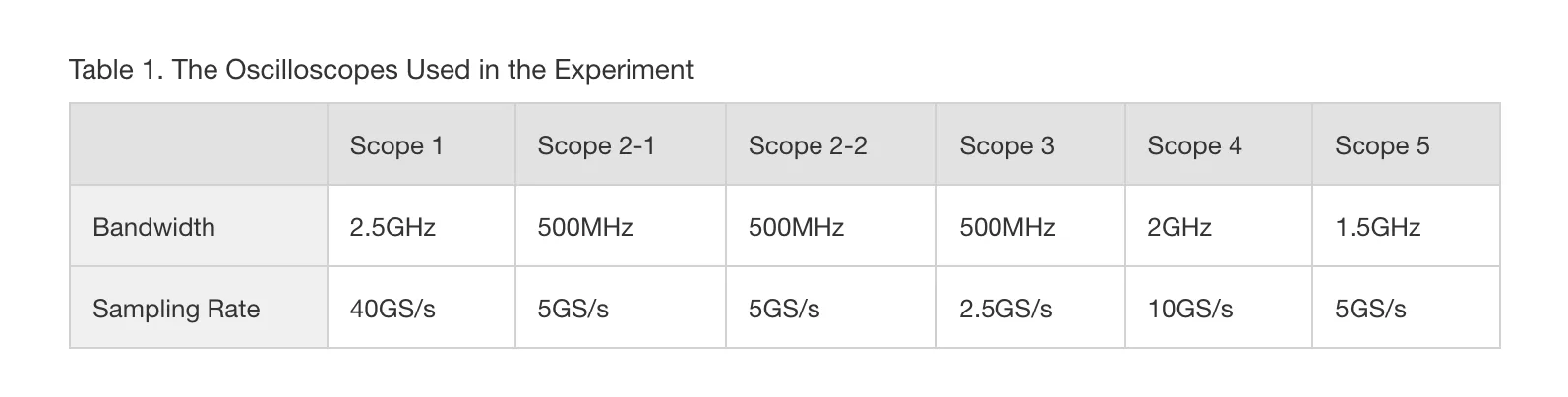
Specification of the oscilloscope used in this experiment is set forth in table 1. The ISO7637-2 standard calls for an oscilloscope with a bandwidth of at least 400MHz, meaning that all oscilloscopes meet the specification.
In the present calibration, the standard waveform was defined as that produced when the amplitude of the ISO7637 3b test pulse was set at around 300V and fine-tuned such that the voltage displayed on oscilloscope 1 using a 40dB attenuator was 1.5V. (The 3b output used was the same in all tests.)
The results of measurement at 50 ohms impedance using an attenuator and coaxial cable are set forth in Table 2. The results of measurement with the different types of oscilloscope via a passive probe calibrated to oscilloscope 1, whereby the base waveform is defined as the waveform measured at 50 ohms with a passive probe and no attenuator, are set forth in Table 3.
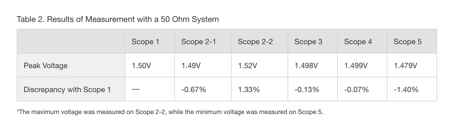
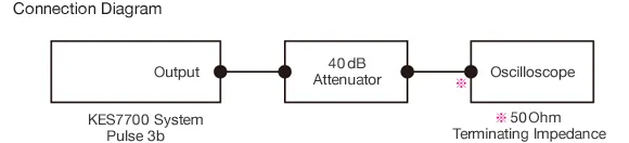
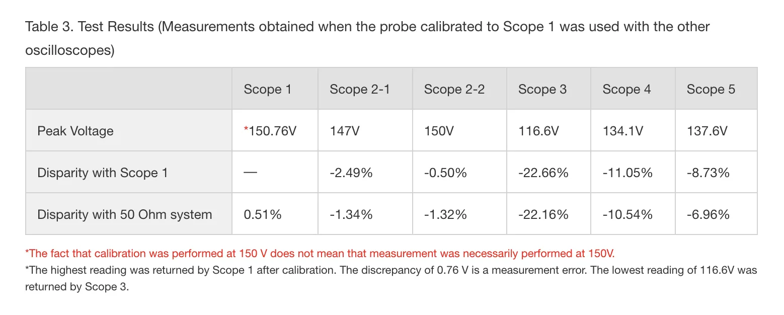
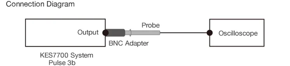
表4-We can see from Table 2 that measurement with a 50 ohm system yielded a maximum voltage of 1.52V and a minimum voltage of 1.479V, representing a variation of ±1.5% against the measured voltage of 1.5V. A variation in that range falls within the margin of error. However, when measurement is performed with a passive probe as per Table 3, a significant disparity may be observed in the measurements. The disparity is as much as 20%, which constitutes a disagreement with the values on the calibration Table.
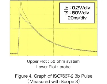
Figure 4, provided for purposes of illustration only, shows the waveform observed upon measurement with Scope 3. The higher peak was obtained when measuring with a 50 ohm system, while the lower peak is a measurement taken with a passive probe. There is a difference in amplitude of over 20%.
The Reason for the Differences in Measurements
Of the oscilloscopes compared, the lowest amplitude measured was yielded with Scope 3, which has the lowest bandwidth and the lowest sampling rate. Let’s look at whether the difference in specification had an effect on the measurements. As mentioned above, oscilloscopes with a high bandwidth and a high sampling rate are suited to the observation of high frequency pulses. Measurements taken with Scopes 4 and 5 using a passive probe come out about 10% lower than measurements taken with Scope 1, despite the two scopes having similar specifications. (Even when compared with measurements performed on the same oscilloscope using a 50 ohm configuration, the measurements taken with the passive probe come out lower.)
What, then, is affecting the peak readings?
In Table 4, I have added the input capacitance parameters for the various oscilloscopes. As you can see, oscilloscopes with high input capacitance tend to return lower readings.
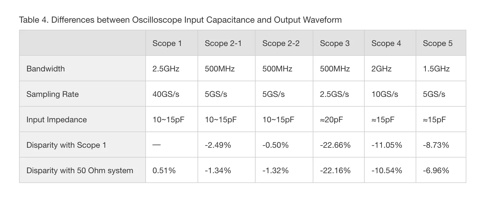 Figure 5 shows the circuit simulator waveforms derived using a simple circuit when the time constant of the pulse generator and probes are fixed while varying the oscilloscopes’ input capacitance.
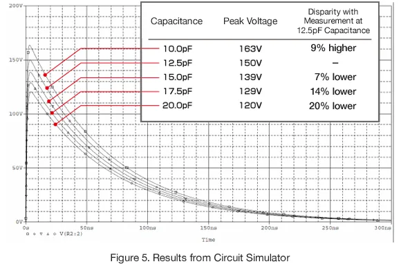
We can see that even a small difference in the oscilloscope’s input capacity produces a difference in peak voltage.
Conclusion
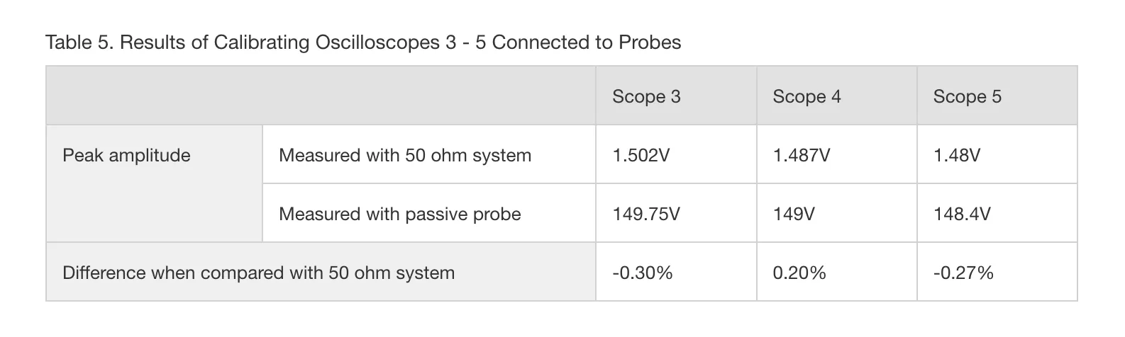
Let me state for the record that these findings do not mean that an oscilloscope with high input capacitance cannot be used to measure high frequency pulses. Provided the oscilloscope is calibrated to the passive probe, waveforms can be measured without any problem at all.
My experiment used as its baseline an oscilloscope owned by Kikusui which had a relatively low input capacitance. Had it, conversely, been based on an oscilloscope with a higher input capacitance, we would have seen higher peak measurements being returned by oscilloscopes that had lower input capacitance. This would probably have prompted us to question the value of oscilloscopes with low input capacitance.
Hopefully the article has demonstrated why calibrating your probe does not guarantee that your measurements will be accurate.