Blocking Diodes and Remote Sensing
My name is Takahiro Miyano and I work in system design and with devices to test the charging and discharging of batteries. In this article, I will share a story about a charge/discharge tester that I initially dismissed as an easy project, only to run into problems later.
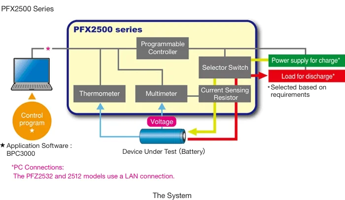
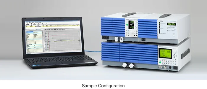
Kikusui’s standard charge/discharge testing system is the PFX2500 series of charge/discharge system controllers. These high-performance controllers combine the charge/discharge control necessary for assessing the electrical characteristics of batteries with Kikusui’s expertise in precision monitoring in one compact package. The PFX2500 allows the user to easily construct a high precision measurement system by combining a Kikusui DC power supply and an electronic load with PFX2500 series. For further details, see the product information on the Kikusui website (PFX series battery testers and capacitor testers).
Working with a Customer-Built Charge/Discharge System Controller
Our client requested us to build a rack-mounted system comprising a DC supply for charging and an electronic load for discharging, attached to a specified external control interface that would connect to a charge/discharge system controller to be built by the client. We assumed that we were only required to perform rack mounting and provide isolated voltage control terminals for external control on the exterior of the rack (rear panel). We also provided a CV (constant voltage) control terminal, a CV monitor terminal, a CC (constant current) control terminal, and a CC monitor terminal, as the client had stated that it would be performing CCCV charging*1 using a DC supply equipped with remote sensing. Because the device would be used to test batteries, we added a reverse polarity prevention (blocking) diode to the system to prevent current from flowing back to the DC supply from the battery after charging. See the excerpt below for more information on reverse polarity prevention diodes.
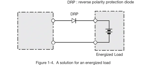
Excerpt from a DC power supply instruction manual regarding energized loads:
Solutions for Energized Loads
When an energized load such as a battery is connected to the system, there is a possibility of current flowing from the load back into the tester circuitry, thereby damaging the tester or shortening the life of the battery.
A reverse polarity protection diode (DRP) is therefore connected in series between the tester and loads of this nature as shown in Fig. 1-4.
*1 CCCV: A charging mode in which the charger operates at constant current for a specified length of time before switching to constant voltage once the battery has reached a predetermined terminal voltage.
An Unintended Discharge Current
Once the rack, DC supply, electronic load, blocking diode, and other parts were ready, we assembled the system in a single step. Now for the moment of truth. We connected the battery to the system. However, once charging was completed, we noticed that a minute discharge current was flowing back from the battery to the DC supply. Because we were using a reverse polarity protection diode, we had not expected any discharge from the bleeder circuit.*2 And yet, a current in the tens of milliamps was flowing back to the supply. Even small currents like this affect a battery. Assuming a wiring error, we set about determining the cause of the issue, referring to our configuration diagram and circuit diagrams.
As mentioned above, the client had specified that recharging would be performed in CCCV mode with remote sensing from the DC supply. It was this remote sensing that was causing the problem. Within the DC supply, the battery output was connected to the bleeder circuit via the remote sensing circuit. The circuit diagram showed that the combined impedance of the remote sensing and bleeder circuits was around 2k ohms. Therefore, the battery was being discharged through this 2k ohm resistance.
Example: Assuming a battery voltage of 45 V, a current of 45 V÷2k Ω, or 22.5mA, would flow through the circuit.
*2 Bleeder circuit: A circuit that rapidly dissipates residual charge on capacitors when the load is removed upon power-down. Some devices allow the bleeder function to be switched on or off.
A Solution for Remote Sensing Leads
This brings me to the solution. We added relay terminals between the remote sensing lead from the DC supply and the battery. By isolating the remote sensing lead from the battery once charging was finished, we were able to eliminate the backflow of discharge current.
I often use a controller from Kikusui’s PFX2500 series to control charging and discharge. The PFX2500 series automates the isolation of the load line from the remote sensing circuitry: in other words, the PFX was taking care of these issues without us having to worry. Because the device described in this article used a charge/discharge controller built by the client (in which the operation of the load line and remote sensing was not synchronized), we overlooked the need to add this function.
The PFX2500 series of recharge and discharge system controllers is designed to enable hassle-free connection and isolation of the DC supply, electronic load and battery. This experience reminded me what a handy device the PFX2500 is. I thought I knew the PFX2500 series inside out, but realized that I will always have more to learn.