The Inconvenient Truth about Electronic Loads
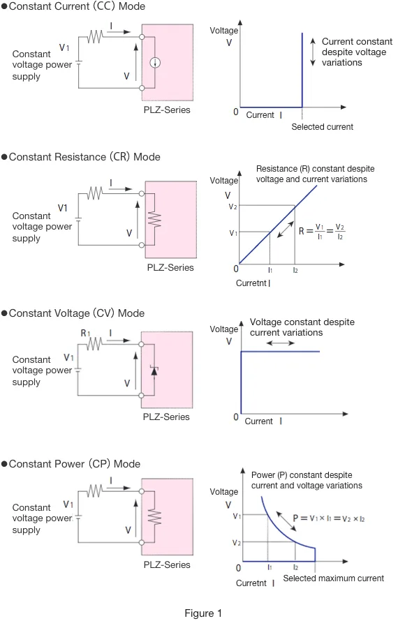
The main modes of operation available on Kikusui electronic loads are set forth in Figure 1. * Generally, the user selects the mode best suited to the device under test or the object of testing.
*Some models also offer a constant current and voltage mode (CC+CV) and a constant resistance and voltage mode (CR+CV).
In fact, load devices harbor an inconvenient truth that no one likes to talk about. When testing power supplies, batteries, and DC/DC converters, a dummy load is required to emulate the current-consuming load or circuit that would be used in reality. Before load devices became commonplace, this role was performed by slide resistors, powerful lightbulbs, or heaters. Dummy loads have drawbacks, however. It is difficult to perform variable load testing and other dynamic tests, and the behavior of the dummy load can differ significantly from real-world loads, making dummy loads unsuitable for detailed testing.
The idea that it would be handy to have a device whose circuits behaved in a similar manner to real-world loads led to the invention of electronic load. While the first electronic loads only offered a choice between Constant Resistance (CR) and Constant Current (CC) modes, these were later joined by Constant Voltage (CV) and Constant Power (CP) modes, which are used for testing rechargeable batteries. These four basic modes are still offered today.
There’s a caveat, however. At the end of the day, the best an electronic load can do is approximate a real load, as real loads do not conform to any single mode of operation, but exhibit compound behaviors. For example, a circuit that initially exhibits a constant current profile may assume a constant voltage profile above a given threshold of voltage. In fact, the selection of modes offered by electronic loads is more a reflection of the types of circuits that are used in these devices than an attempt to emulate objects under test.
Take off the rack clothing, for example, which generally comes in small, medium, and large. While these sizes fit some people perfectly, for the majority it’s usually slightly too large or small, but they choose to wear it anyway. The same can be said of the standard testing modes offered by electronic loads. While suppliers like to give the impression that they are offering you choices, the options available have in fact been selected to suit the supplier. (I hope I didn’t cross a line by writing that!)
I am of course not suggesting that the manufacturers of electronic device are completely dishonest. Rather, manufacturers offer features that cater to the lowest common denominator because doing so offers a cost advantage, and because devices with more straightforward settings are easier to use. I should qualify my earlier statement by saying that the electronic loads currently available on the market do serve a purpose!
Using the Non-Linear Arbitrary (ARB) Mode to Realistically Emulate Loads
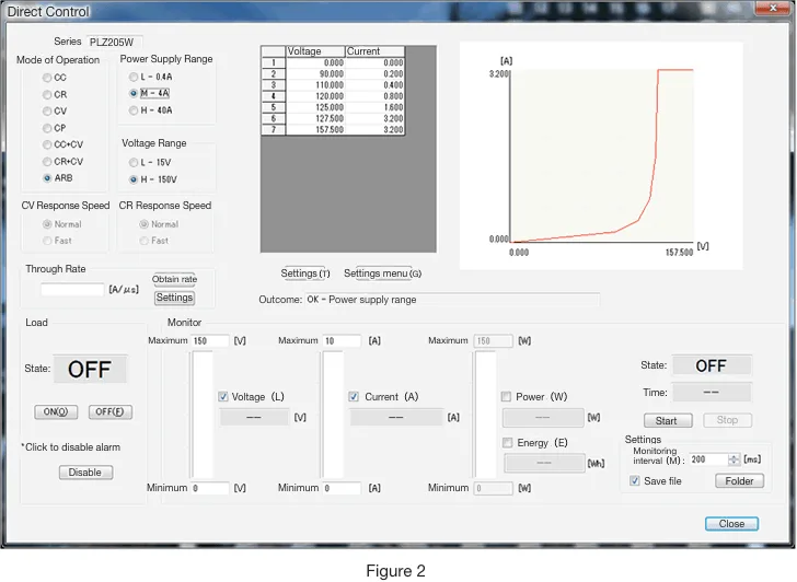
Recently, Kikusui released a revolutionary new series of electronic loads, the PLZ-5W. In addition to the four standard modes, the PLZ-5W adds a non-linear, arbitrary waveform mode that allows the user to stipulate any current-voltage profile by plotting a graph of the desired characteristics and converting it into a table.
Figure 2 depicts a sample program in ARB mode that has been created using the optional software package, Wavy for PLZ-5W, showing the kind of exponential behaviors that can be simulated.
For example, programming the PLZ-5W with the following data allows you to simulate the forward-current characteristics of a diode:
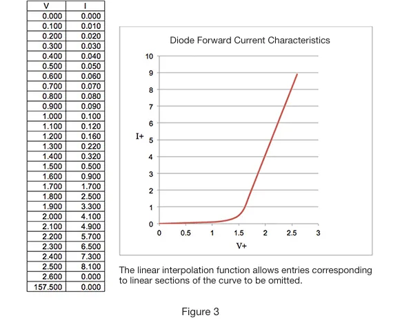
When inputting a profile into the PLZ-5W, values must be specified up to 157.5 volts on the horizontal axis. In the above example, we simply enter “157.500V” in the voltage field under the box that reads “2.600 V” and “0.000” in the relevant current fields to yield a linear (zero) current between 2.6 V and 157.5 V.
In the same way, when evaluating generators and similar devices, the PLZ-5W can emulate a situation where the current is a constant 10 amps between 0.1 and 5.0 volts, then decreases parabolically, ultimately reaching zero at 10 volts. (Figure 4)
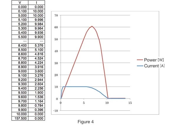
In the case above, current rises linearly from zero and then falls in a non-linear fashion once the voltage exceeds 5 volts, so we can obtain a power-voltage (PV) characteristic curve that peaks at about 60 watts before falling back down to zero. The power-logging function of the PLZ-5W series enables this P-V curve to be plotted without the need to organize separate measuring equipment.
While not realistic, even the parabolic profile below is able to be emulated. (Who knows—someone out there might actually do this.)
The PLZ-5W enables you to not only emulate actual loads, but also to test theoretical values and perform fun experiments to create conditions not possible in the real world. The possibilities are limited only by your imagination. If you are interested in seeing a demonstration model, please contact our sales team.